


F08D/F10D
F08D/F10D
5-10
5-10
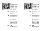
5.3.3 Arrêt du chauffage et
du système d´aération
(1) Fermer l´amenée d´air chaud
(5-7/flèche).
(2) Mettre l´interrupteur à bascule
(5-5/flèche) pour ventilateur en
position "0".
5.3.4 Quitter le véhicule
(1) Vérrouiller les leviers à main
pour l´hydraulique de travail et l´hy-
draulique accessoire (1-2/flèches).
(2) Retirer la clé de contact et
fermer les portes.
5.4
Réglage du siège du
conducteur
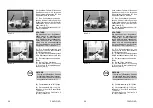
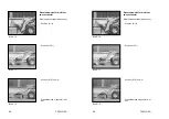
(1) Régler l´inclinaison du dossier
ou abattre le dossier à l´aide du
levier (5-8/2).
(2) Régler la hauteur et l´inclinaison
du siège à l´arrière tout en tirant le
levier (5-8/3) vers le haut.
(3) Régler la hauteur et l´inclinaison
du siège à l´avant tout en tirant le
levier (5-8/4) vers le haut.
(4) La suspension à ressorts du
siège peut être réglée à l´aide d´une
roue à main (5-9/1) et adaptée au
poids du conducteur (40 ... 130 kg).
(5) Déterminer la hauteur de l´accou-
doir avec la poignée tournante (5-8/1).
(6) Le cas échéant, régler de
nouveau la position des transmet-
teurs de soupape pour l´hydraulique
de travail (4-10/8) et l´hydraulique
accessoire (4-9/6).
(7) Tout en tirant l´arceau (5-9/2)
vers le haut et en déplaçant en même
temps le siège vers l´avant ou l´arrière,
le siège du conducteur peut être
ajusté dans sa position horizontale
selon les besoins du conducteur.
5.3.3 Arrêt du chauffage et
du système d´aération
(1) Fermer l´amenée d´air chaud
(5-7/flèche).
(2) Mettre l´interrupteur à bascule
(5-5/flèche) pour ventilateur en
position "0".
5.3.4 Quitter le véhicule
(1) Vérrouiller les leviers à main
pour l´hydraulique de travail et l´hy-
draulique accessoire (1-2/flèches).
(2) Retirer la clé de contact et
fermer les portes.
5.4
Réglage du siège du
conducteur
(1) Régler l´inclinaison du dossier
ou abattre le dossier à l´aide du
levier (5-8/2).
(2) Régler la hauteur et l´inclinaison
du siège à l´arrière tout en tirant le
levier (5-8/3) vers le haut.
(3) Régler la hauteur et l´inclinaison
du siège à l´avant tout en tirant le
levier (5-8/4) vers le haut.
(4) La suspension à ressorts du
siège peut être réglée à l´aide d´une
roue à main (5-9/1) et adaptée au
poids du conducteur (40 ... 130 kg).
(5) Déterminer la hauteur de l´accou-
doir avec la poignée tournante (5-8/1).
(6) Le cas échéant, régler de
nouveau la position des transmet-
teurs de soupape pour l´hydraulique
de travail (4-10/8) et l´hydraulique
accessoire (4-9/6).
(7) Tout en tirant l´arceau (5-9/2)
vers le haut et en déplaçant en même
temps le siège vers l´avant ou l´arrière,
le siège du conducteur peut être
ajusté dans sa position horizontale
selon les besoins du conducteur.
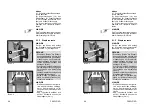
5.3.3 Switching off the heat-
ing and ventilation system
(1) Shut off the warm air supply
(5-7/arrow).
(2) Turn the rotary switch (5-5/
arrow) to the “0” position.
5.3.4 Leaving the loader
(1) Lock the hand levers for
working and additional hydraulics
(1-2/arrows).
(2) Remove the ignition key and
lock the doors.
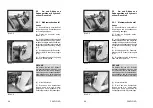
5.4
Adjusting the
operator’s seat
(1) Adjust or swing forward the
back support using the hand lever
(5-8/2).
(2) Adjust the rear seat height and
inclinationby lifting the hand lever
(5-8/3).
(3) Adjust the front seat height
and tilt by lifting the hand lever
(5-8/4).
(4) The seat suspension can be
adjusted to the driver's weight
(40 - 130 kg) using the hand wheel
(5-9/1).
(5) Adjust the height of the arm
rest by turning the knob (5-8/1).
(6) If necessary, re-adjust the
position of the valve levers for the
working hydraulics (4-10/8) and the
additional hydraulics (4-9/6).
(7) The operator’s seat can be
adjusted in the horizontal direction
to suit the driver's requirements by
lifting the handle (5-9/2) and moving
the seat forward or backward.
5.3.3 Switching off the heat-
ing and ventilation system
(1) Shut off the warm air supply
(5-7/arrow).
(2) Turn the rotary switch (5-5/
arrow) to the “0” position.
5.3.4 Leaving the loader
(1) Lock the hand levers for
working and additional hydraulics
(1-2/arrows).
(2) Remove the ignition key and
lock the doors.
5.4
Adjusting the
operator’s seat
(1) Adjust or swing forward the
back support using the hand lever
(5-8/2).
(2) Adjust the rear seat height and
inclinationby lifting the hand lever
(5-8/3).
(3) Adjust the front seat height
and tilt by lifting the hand lever
(5-8/4).
(4) The seat suspension can be
adjusted to the driver's weight
(40 - 130 kg) using the hand wheel
(5-9/1).
(5) Adjust the height of the arm
rest by turning the knob (5-8/1).
(6) If necessary, re-adjust the
position of the valve levers for the
working hydraulics (4-10/8) and the
additional hydraulics (4-9/6).
(7) The operator’s seat can be
adjusted in the horizontal direction
to suit the driver's requirements by
lifting the handle (5-9/2) and moving
the seat forward or backward.
Summary of Contents for AF 100
Page 61: ...F08D F10D F08D F10D Beschilderung Beschilderung Signalisation Signalisation Signs Signs ...
Page 76: ...F08D F10D F08D F10D 2 8 2 8 Schriftzug Lärmarme Baumaschine Schriftzug Lärmarme Baumaschine ...
Page 104: ...F08D F10D F08D F10D Beschreibung Beschreibung Description Description Description Description ...
Page 177: ...F08D F10D F08D F10D Wartung Wartung Entretien Entretien Maintenance Maintenance ...
Page 219: ...F08D F10D F08D F10D Störung Ursache und Abhilfe Störung Ursache und Abhilfe ...
Page 222: ...F08D F10D F08D F10D Dérangements causes et remèdes Dérangements causes et remèdes ...
Page 225: ...F08D F10D F08D F10D Malfunctions causes and remedies Malfunctions causes and remedies ...
Page 228: ...Anhang Anhang Appendice Appendice Appendices Appendices ...
Page 229: ......
Page 230: ......
Page 237: ......
Page 242: ...F08D F10D F08D F10D A 10 3 A 10 3 ...
Page 243: ...F08D F10D F08D F10D B 10 3 B 10 3 ...
Page 244: ...F08D F10D F08D F10D C 10 3 C 10 3 ...
Page 245: ...F08D F10D F08D F10D D 10 3 D 10 3 ...
Page 246: ...F08D F10D F08D F10D E 10 3 E 10 3 ...
Page 247: ...F08D F10D F08D F10D F 10 3 F 10 3 ...


