background image

Mini Merlin Installation, Operation & Maintenance                                                                                                                              


Rev: 03 05-22 

7  

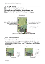
Circuit Board Overview 


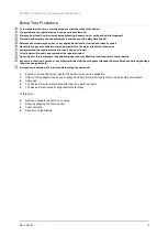
Damage to PCBs when creating cable entry points may void any warranty! 


Take care when making connections to high voltage connectors! 


Any damage attempting to remove the circuit board may void any warranty! 


All Class 2 wiring is to be installed within flexible tubing to maintain segregation between circuits! 


Wiring of different circuits shall be separated by means of routing, clamping or barrier! 


For field connections other than connected Heat detectors use wires suitable for at least 167°F (75°C)  


Wiring 

 Gas Solenoid Valve 


When the installation includes a standing pilot, ensure the internal auto reset dip switch is in the OFF position requiring a 
manual reset of the fuel supply! 
 

A gas solenoid valve should be powered using the terminals marked [VALVE OUT]. When the valve out terminal is 
wired to a normally closed (NC) gas solenoid valve, the device can be used to isolate the gas supply for multiple 
appliances. Use an external transformer (not supplied) to close a 24VAC gas solenoid valve that could supply gas to 
one or more appliances. 


Gas Supply Controlled by 100-120VAC Solenoid Valve                        Gas Supply Controlled by 24VAC Solenoid Valve 


Summary of Contents for Mini Merlin CH4CO v2-TX

Page 1: ...CO v2 TX Dual Gas Detector Installation Operation Maintenance Manual Please read this manual carefully and retain for future use For specific requirements that may deviate from the information in this guide contact your supplier American Gas Safety LLC www americangassafety com ...

Page 2: ...ircuits 8 Wiring Adaptable Outputs 8 Wiring Pilot Water Heater Boiler Limit Breaker 9 Wiring Remote Shut Off 9 Auto Reset Buzzer Switches 9 Building Management System 10 Operation 10 Initial Power Up 10 Digital Indications 10 Alarm Set Points 10 Alarm Reset 11 Remote Shut Off Indication 11 Manual Circuit Simulation Test 11 End of Operational Life EOL 11 Maintenance 12 Cleaning 12 Manual Circuit Si...

Page 3: ...th specific medical conditions If in doubt consult a doctor physician Your product should reach you in perfect condition if you suspect it is damaged contact your supplier Warranty Statement Warranty Coverage The manufacturer warrants to the original consumer purchaser that this product will be free of defects in material and workmanship for a period of two 2 years from date of purchase The manufa...

Page 4: ...y ventilated Automobiles gas stoves water heaters portable fuel burning heaters fireplaces Blocked chimneys or flues corroded or disconnected vent pipes Burning charcoal or fuel in grills in an enclosed area or near the home Methane General Information Methane is non toxic and it can be harnessed as an energy source However methane is highly explosive and it can cause death by asphyxiation Methane...

Page 5: ... positions determined by those who have knowledge of gas dispersion the process plant system and equipment involved and in consultation with both safety and electrical engineering personnel Take in to account the design of the air flow patterns within the zone area Detectors should be installed in the correct orientation as recommended by the manufacturer and ease of access should be accounted for...

Page 6: ...g electrical box Restrain the hazardous live wiring from accidental loosening to prevent wires from moving after installation and touching parts of opposite polarity or at low voltages Isolate the equipment from all hazardous live power sources before opening the cover 1 Carefully remove the front cover from the unit by using an M3 socket wrench 2 Using the rear base mark mounting holes to the wal...

Page 7: ... than connected Heat detectors use wires suitable for at least 167 F 75 C Wiring Gas Solenoid Valve When the installation includes a standing pilot ensure the internal auto reset dip switch is in the OFF position requiring a manual reset of the fuel supply A gas solenoid valve should be powered using the terminals marked VALVE OUT When the valve out terminal is wired to a normally closed NC gas so...

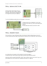
Page 8: ...liance Multiple appliance limit switches can be wired in series Wiring Adaptable Outputs The mini merlin can be used to effect external relays and contactors to disable multiple appliances when a fault condition is detected Multi pole relays can interrupt power to electrical circuits controlling boiler valves and pumps Low voltage wiring is to be inserted into the external limit circuit of a gas a...

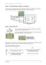
Page 9: ...rmally closed and will alarm when energised open isolating the gas supply When using this input only the mains utility output shall de energize If you are using the CO or NG relay to shut down a boilers external limit circuit you will need to wire the input in series with the relay output Auto Reset Buzzer Switches ON OFF Auto Reset In the event of a power loss the mini merlin will restart automat...

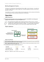
Page 10: ...ouch sensor on the front cover for 3 seconds The detector enters a stabilisation phase for approximately one minute during this period the device is not operational If the detector has been configured to Auto Reset your device will power up automatically when electrical power is supplied To turn your device off remove isolate electrical power supply Digital Indications Alarm Set Points When the de...

Page 11: ...ch button is pressed and held during normal operation the mini merlin will simulate an open circuit to ensure all configured systems outputs alarms indications and other external devices operate as intended in response to gas End of Operational Life EOL The EOL is approximate from the first five 5 hours of continuous power The EOL will depend on the type of gas your detector is targeting and may v...

Page 12: ...y briefly exposing the unit to a known concentration of the target gas that usually exceeds the highest alarm point If the detector goes into alarm and all signals outputs activate then the system is working safely If the system fails to operate as intended in an alarm state the gas detector must not be used until a full inspection and service has been conducted NFPA requires all gas detectors to ...

Page 13: ...cylinder All cylinders will re seal upon removal of the regulator valve Deviating from this test process is deemed improper and may affect the functional safety of your device Exposure to chemicals smoke or any other materials other than the gases intended to be monitored can seriously damage the gas sensing elements Always allow a minimum of 5 minutes before testing the same unit 1 Ensure you hav...

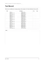
Page 14: ...tch Cylinder No CH4 NG LEL Batch Cylinder No CO ppm Batch Cylinder No CH4 NG LEL Batch Cylinder No CO ppm Batch Cylinder No CH4 NG LEL Batch Cylinder No CO ppm Batch Cylinder No CH4 NG LEL Batch Cylinder No CO ppm Batch Cylinder No CH4 NG LEL Batch Cylinder No CO ppm Batch Cylinder No CH4 NG LEL Batch Cylinder No CO ppm Batch Cylinder No CH4 NG LEL Batch Cylinder No CO ppm Batch Cylinder No CH4 NG...

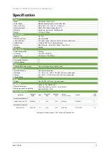
Page 15: ...Fuse Anti Surge 3 15A 250Vac Equipment Overvoltage Category II Pollution Degree 2 Relays Volt Free BMS relay output 0 5A switching current resistive load Environmental Ingress Protection Not Formally Evaluated Operating 10 50 C 14 122 F 30 80 RH non condensing Storage 25 50 C 13 122F up to 95 RH non condensing Altitude Rating 2000m Wiring Typical Min 18AWG 75 C min Tinned copper Approvals Electric...

Page 16: ...ended and is free from any unforeseen damage caused by transit installation Every effort is made to ensure the accuracy of this document however AGS can assume no responsibility for any errors or omissions in this document or their consequences AGS would greatly appreciate being informed of any errors or omissions that may be found in the content of this document For information not covered in thi...

Reviews: