background image

19/09/18 


Page 24 of 67 


ASR650 Operational Manual


4.1 

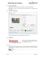
Installing ASR-PC-Demo 

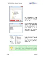
Please start the setup file and follow the instructions in order to install the software. 
 

ASR-PC-Demo

  is  written in Visual Studio and requires the  Microsoft  .NET Framework Version 

3.5 or higher. 
 

4.2 

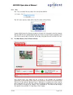
Starting the ASR-PC-Demo 


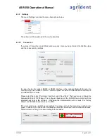
After starting the software, the main screen appears as shown above. 


4.3 

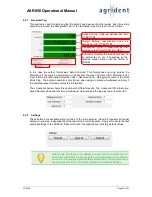
The File Menu 


The file menu is located in the upper left corner of 
the  main  window.  It  consists  of  the  menu  items 

File

’, ‘

Settings

Tools

 and 

?

’. 


4.3.1 

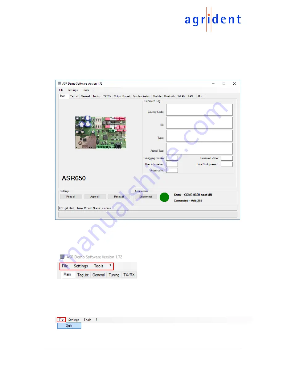
File 

The Menu 

File

’ contains only one menu item: ‘

Quit

’. This item closes the software. Alternatively, 

you might also close the program using the corresponding 

‘X’ button in the upper right corner of 

the main window. 


Summary of Contents for ASR650

Page 1: ...19 09 18 Page 1 of 67 Agrident GmbH Steinklippenstr 10 D 30890 Barsinghausen Phone 49 5105 582573 10 Fax 49 5105 582573 17 ASR650 Stationary Long Range Reader V19 09 18 ...

Page 2: ...onic mechanical photocopying recording or otherwise without prior written permission of Agrident GmbH Agrident GmbH reserves the right to make changes to any and all parts of this documentation without obligation to notify any person or entity of such changes September 2018 Agrident GmbH Steinklippenstr 10 30890 Barsinghausen Germany Phone 49 0 51 05 582573 10 Fax 49 0 51 05 582573 17 E Mail mail ...

Page 3: ...bars 15 3 The Reader Electronics 16 3 1 Specifications 16 3 2 Installing and Connecting the ASR650 17 3 2 1 ST2 Connector for DC power supply and interface 17 3 2 2 ST7 Antenna Connector 18 3 2 3 ST6 Connector for external LED Board 18 3 2 4 ST3 Connector for 4 8 channel antenna multiplexer 19 3 3 Signalization 19 3 4 Power Supply Requirements 20 3 5 The RS232 Interface 21 3 6 The RS485 Interface ...

Page 4: ...iming 40 4 6 6 Device Check 41 4 6 7 Baud Rate 41 4 6 8 Processing Priority 42 4 6 9 Zero Tag Output 42 4 7 Tuning 43 4 7 1 Power On Tuning 43 4 7 2 Background Tuning 43 4 7 3 Tuning Data 44 4 7 4 Tuning Graph 44 4 7 5 Start Tuning 46 4 8 TX RX 48 4 8 1 RF Activation 48 4 8 2 RF Power 49 4 8 3 Receiver sensitivity 49 4 9 Output Format 50 4 9 1 Introduction 50 4 9 2 Changing the output format 50 4 ...

Page 5: ...10 1 3 Wired Sync Mode 58 4 10 1 4 Wired Sync Slave only 58 4 10 1 5 Wired Sync Triggered 58 4 10 2 Wireless Sync Level 59 4 11 Module 62 4 12 Bluetooth 62 4 13 WLAN 63 4 14 LAN 63 4 15 Mux 64 5 Safety and care 65 6 Warranty 65 7 CE MARKING 66 8 FCC and IC digital device limitations 66 9 Trouble shooting 67 ...

Page 6: ...sponders using an internal or external antenna The reader generates a high frequency field in order to get the data of a transponder The received data are transmitted to an external controller e g PC via an interface Transponder Data carrier for RFID applications available in various models and types Raw data Complete data content of a transponder that means ID and additional information for examp...

Page 7: ...the antenna and the environment The following things may influence the reading range Mounting antenna on metal or close to metal Antenna mistuned Electrical interference The ASR Demo Software includes tools for checking the tuning state of the antenna and the environmental noise 1 3 Supported transponder types The ISO 11784 11785 supports two types of transponders FDX B and HDX Both work completel...

Page 8: ...seriously The integrated Autotuning function of the reader is able to compensate parts of the negative influence of the metal Metal normally decreases the antenna inductance This can be adjusted by the reader by adding more capacitance to the antenna circuit However the losses in the metal cannot be compensated and reduce the reading range even if the antenna is tuned correctly So it should be avo...

Page 9: ...the plastic frame Please avoid exposing the antenna to direct sunlight permanently Installing the antenna in an area sheltered from ultraviolet light will extend its durability Please ensure that the antenna and the antenna cable do not interfere with movements of animals or persons close to the system The antenna cable should be fastened with cable ties or it should be inside protective pipes Ple...

Page 10: ...211 or IGUS Chainflex CFBUS LB 021 very flexible also at low temperatures but more expensive 2 1 5 Field Distribution 1 Single Antenna The left picture shows the field distribution and lines of flux for a single antenna This leads to optimum and worst reading orientations Generally speaking the transponder coil should be in 90 degrees to the field lines in order to achieve the best reading range I...

Page 11: ... certain distance to the metal plate in order to avoid a complete loss of reading performance into the other direction The distance depends on the antenna size For the APA206 for example the antenna should have at least 10 centimeter clearance from the metal plate For larger antennas the distance has to be higher This graph shows the field distribution of a single loop antenna close to magneticall...

Page 12: ...s are in phase This is also called parallel or Helmholtz antenna The optimum tag orientation is similar to the one of the single antenna transponder coil parallel to the panels The reading distance can be significantly increased compared to a single antenna In addition it does not matter on which side of the animal the ear tag is attached since the tag is close to any of both panels Please avoid v...

Page 13: ...ing the antennas in positions where the animals transponder stays in this dead spot For pure walkthrough applications this fact does not really matter because the tag should be read without stopping the animal before and after this spot But for applications where animals should be read when they are stopped e g in a scale it should be considered carefully Additionally the field is pretty much push...

Page 14: ...nce is lower the reader will disable the transmitter in order to protect some components from damage due to overheating A low antenna impedance results from a low antenna Q In case of using Agrident antennas the values for the impedances are high enough But when the antenna is too close to metal the impedance decreases as well In this case please check your installation and try to mount the antenn...

Page 15: ...shifted upwards so that the lower horizontal part of the coil is directly at the position of a metal bar This setup is worse compared to 1 and it will introduce higher losses that will result in lower reading performance 3 The installation shown here will introduce even more losses because now the upper and lower horizontal parts of the coil have the same position as the steel bars 4 5 4 Here the ...

Page 16: ... on modules like Bluetooth WLAN Ethernet or the two channel antenna multiplexer The optional wired Synchronization module can be attached to another connection strip 3 1 Specifications Item Specification Power Supply 12V 3A DC to 24V 1 5A DC 5 Operating Frequency 134 2kHz Reading Range HDX up to 70cm FDX B up to 65cm with antenna APA203 Reading Rate HDX up to 14 reads per second FDX B up to 18 rea...

Page 17: ...nna connector Since the Add On Modules do only fit in one direction the pin assignments do not need to be explained in detail The ASR650 uses the Phoenix Combicon series for the antenna power supply and interface connectors The reader board comes with the corresponding mating plugs which have screw terminals for connecting all the cables The wiring has to be done as follows 3 2 1 ST2 Connector for...

Page 18: ...rnal use only 4 Yellow LED cathode 5 For internal use only 6 Green LED cathode 7 For internal use only 8 GND The external LEDs have the same functions as the on board LEDs Please note that there are series resistors for the red and yellow external LEDs on the reader board already but not for the green LED Hence the series resistor for the external green LED must be added externally It is important...

Page 19: ...t as possible 3 3 Signalization The ASR650 has three on board LEDs which indicate the reader status In general the yellow LED indicates that the reader is switched on and the Firmware is running the green LED indicates a successful tag read and the red LED means that there is a fault condition The table below lists the possible indications related to the operating conditions Yellow Power Green Rea...

Page 20: ...power supply unit PSU is 12 0 Volts and you want to use standard data cable with a cross section of 0 5mm The minimum input voltage for the reader is 11 0 Volts and the maximum possible current about 2 Ampere So the maximum allowed voltage drop is 1 0 Volt and thus the maximum allowed cable resistance is 0 5 Ω VPSU 12 0V VIn Minimum 11 0V cable 0 5 with 36mΩ meter IMax 2 0A 𝑙𝑀𝑎𝑥 𝑉𝑃𝑆𝑈 𝑉𝐼𝑛 𝐼𝑀𝑎𝑥 2 0 ...

Page 21: ...ader to a 9 pole D SUB connector please use the following wiring ASR550 ST2 Connection PC SUB D 9 pole Pin 3 TxD Pin 2 RxD Pin 4 RxD Pin 3 TxD Pin 5 GND Pin 5 GND Please do not forget to connect the Ground line as this builds the reference for RxD and TxD The V Pin ST5 Pin2 is not the same as Ground The RS232 will not work properly without connecting Ground In addition you always have to connect b...

Page 22: ...d pair cable like CAT5 Ethernet cable for the RS485 wiring only A and B should be connected to one twisted pair Although an RS485 signal has no ground reference GND should be connected as well Over long distances there can be significant differences in the voltage level of Ground RS 485 networks can typically maintain correct data with a difference of 7 to 12 Volts If the Grounds differ more than ...

Page 23: ... use the same and correct setting It is very important that each device on the bus uses a different network or node address If several readers are using the same address data collision might be the result You can change the reader s node addresses via the ASR PC Demo Software 4 ASR650 Settings In order to allow the ASR650 to work in a wide range of applications there are lots of possibilities for ...

Page 24: ...or higher 4 2 Starting the ASR PC Demo After starting the software the main screen appears as shown above 4 3 The File Menu The file menu is located in the upper left corner of the main window It consists of the menu items File Settings Tools and 4 3 1 File The Menu File contains only one menu item Quit This item closes the software Alternatively you might also close the program using the correspo...

Page 25: ... This also applies to all kind of USB Serial Converters like an USB RS232 Converter Please select the correct Port Name and the correct Baud Rate The baud rate is configurable between 9600 and 115200 baud The configured baud rate of the ASR650 has to match with the selected baud rate in the software otherwise the communication will not work Per factory default the ASR650s baud rate is set to 9600 ...

Page 26: ...an for compatible devices on all available ports and with all possible baud rates As soon as a device was found the window shows the device type and on which port the reader was found with a particular baud rate Click on search in order to start the scan Depending on how many ports are available on the system the search might take a while When the device of interest was found the scan maybe aborte...

Page 27: ...u want to evaluate diagnosis data offline i e with no reader connected The ASR650 saves the diagnosis data also tuning curves different from the previous models like the ASR400 ASR500 ASR600 and ASR700 When diagnosis data should be evaluated without having a reader connected please ensure that you select the correct reader model here otherwise the data will not be shown correctly 4 3 2 5 Sound ASR...

Page 28: ...n t be explained in this manual but in further documentation 4 3 3 1 Monitor The Monitor window shows the complete serial communication between the reader and the PC This is very useful for software developers in order to verify communication in their own software with the telegrams the ASR PC Demo software is sending and receiving The communication might also be watched in ASCII format This makes...

Page 29: ...efault name Animal Counter followed by date and time You might also change this default name of course If you pressed Cancel the Animal Counter is started anyway but no file will be saved This information is also displayed in the Animal Counter window If you decided to save a file the path will be displayed When you are reading transponders now the counter is increased as soon as a new unknown tag...

Page 30: ... antenna 2 Electromagnetic interference often referred to as noise The ASR650 provides powerful diagnosis features for evaluating both antenna status and noise levels However since these features might not be that easy to use manually for non experts there is a simple way for getting all these data the Auto Diagnosis It stores a complete tuning curve and the noise levels for both receivers FDX and...

Page 31: ... diagnosis data to the technical staff You may also pack the files using WinZip WinRar or a similar program The folder that was created at the chosen destination should contain the files shown on the left These files provide information about the complete reader status at the point of sampling the data In case of technical problems especially problems with the reading performance please provide as...

Page 32: ...device But anyway the update can also be started from here 4 4 The Main Window of the PC Demo Software After ASR PC Demo was started and the connection to the ASR650 was established successfully you should see a screen similar to the one above The main screen consists of the File menu 1 the sections Received Tag 2 Settings 3 Connection 4 and an area for status messages Info 5 which also contains a...

Page 33: ...also called Species Code Reserved Zone Retagging Counter or the Data Block Flag The antenna number is only shown when using an antenna multiplexer and only if the selected output format contains this information The screenshot below shows this section with different results The Advanced ISO information have different values and this time a multiplexer was used and the tag was read on antenna 3 4 4...

Page 34: ...seconds please check your port settings again The program could connect to a reader successfully The complete reader settings from all tabs are requested and the values in ASR PC Demo are updated accordingly 4 4 4 The Info area This section is used for displaying status messages In addition there is a progress bar indicating the status of the operation to be executed In this example the request fo...

Page 35: ... Counter 6 When a new transponder is read it will be added to the list in this case this would be Nr 21 In case a known tag is read again the blue marker 7 will switch to the according line in the list The Counter 6 is incremented each time this ID appears again Tag Type 4 and Antenna Nr 5 can only be displayed if the reader uses an output format that transmits this information The list can be emp...

Page 36: ... on the printed circuit board The Firmware version of the reader is shown below The get buttons only request these particular settings while Read all will request all reader settings The set buttons function accordingly 4 6 2 Transponder Types Since the ASR650 is a reader according to the ISO11784 11785 regulations it can read FDX B and HDX transponders Anyway if you do not want to read either of ...

Page 37: ...upport anti collision For such applications you either have to use Requested ID output or Trigger Mode The Continuous ID output mode is intended to be used for point to point connections only This does not apply if you are using the Ethernet or WLAN option since these interfaces do support anti collision The Continuous ID output mode was called Master Mode for the previous reader generations The D...

Page 38: ...different network addresses first using a point to point connection Please see chapter 4 6 4 Device Addresses for details The Last_ID requests to the different readers have to contain the corresponding reader address as destination address If you have to implement this into your own software the ASR650 protocol description provides further helpful information If the reader is set to this operating...

Page 39: ...ps FF 12750ms Maximum value If a transponder was read before the Timeout has elapsed the ASR650 will immediately switch off its RF field and return the tag number The Delaytime is greyed out because it does not have a meaning in case of using the Trigger Mode If the reader is configured to work in the Trigger Mode there is an additional pushbutton in the Received Transponder area of the Main tab g...

Page 40: ... timing FDX tag present HDX tag present Field On time Field Off time No No 50ms 4ms Yes No 50 100ms 4ms No Yes 50ms 20ms Yes Yes 50 100ms 20ms A field on period followed by a field off period can be called slot or cycle In the Variable timing every 10th cycle is 50 20 milliseconds fixed This should allow wireless synchronizing handheld readers to read an HDX tag at least once a second However ther...

Page 41: ...mitter voltage is lower the antenna voltage will be lower accordingly If the antenna impedance is lower the antenna voltage will be smaller as well Press Device check in order to get the latest measured voltages from the reader In case of a fault condition the corresponding text field will turn orange This is an example for a low input voltage As a result the antenna voltage is 0V because the read...

Page 42: ...n and too fast leads to a reduced reading speed because each request can result in the abortion of the current reading cycle 4 6 9 Zero Tag Output This section contains the settings that deal with tag outputs from the reader when no tag has been read successfully By setting the checkbox ON the reader is configured to always sending empty tags repeatedly about every 50 milliseconds This allows the ...

Page 43: ...wer On Tuning decides if the ASR650 will perform a complete Autotuning procedure after switching on or not This tuning takes less than 200ms and is enabled per factory default 4 7 2 Background Tuning The ASR650 is capable of changing its tuning value automatically if the environment regarding the presence of metal changes This may take a few seconds but does not require any manual action This opti...

Page 44: ...na inductance by setting more tuning capacitors The Status field gives further information in case of an antenna fault In this example it says OK because there is no antenna fault The antenna impedance is a very important value If this is too low for the selected power level the reader will disable the antenna Please also refer to chapter 2 1 6 You might request these values once by pressing the g...

Page 45: ...case an antenna multiplexer is used Pressing the Request Curve button will force the software to request the tuning curve again The find button in the Marker box will set a permanent marker on the Capacitor Pattern which is currently used by the reader You might change the scaling of the amplitude as well For the ASR650 the default setting of 0 100V makes the most sense if the antenna status is ok...

Page 46: ...ge is falling If the tuning of the antenna is ideal the reader uses a Capacitor Pattern of 9 to 11 the yellow LED will be activated very shortly followed by the green LED and a longer period of the red one This is because 9 10 or 11 are pretty much on the left side of 64 possible combinations Let s have a look at some example curves The above shown curve has shown a maximum voltage at Capacitor pa...

Page 47: ...s caused by too much metal Even if the reader is still able to tune for the correct resonant frequency there will be a reduced reading performance So you should always try to modify your application in a way that there are no losses like this In case the ASR650 is used at maximum transmit power the minimum required antenna impedance is 750Ω In the screenshot on the left side it is only slightly ab...

Page 48: ... be used too often since the new operating mode will always be written into the readers non volatile memory which has a limited amount of write cycles Flash Memory So if your application requires enabling and disabling the RF field many times a day you should use this command It will not be written into the non volatile memory just into the RAM hence this setting is only active as long as the read...

Page 49: ...ult value of 100 means that the receivers are operating at full sensitivity Select the desired sensitivity and confirm with set or request the currently configured value via get This has to be done for FDX and HDX in case both technologies should be used The button auto adj helps to find the correct setting when the required reading range is known Place the tag in front of the antenna at the desir...

Page 50: ...in order to get the information out of the telegram The following output formats work with the transmission frame ASCII Byte structure Compact coding Raw data There are also formats which work without the transmission frame These formats are recommended if the reader has to work with a scale or in applications where it is not possible to use the standard protocol The following formats work without...

Page 51: ...ut In the above screen one can see that the default value for ID Code is Unformatted In this case the reader transmits the 64 Bit transponder raw data in hexadecimal notation Below the Custom Format configuration box you can see a preview of your selected output format In Unformatted you can only select a Field Delimiter a Command Prompt and it is possible to send the antenna number which is inter...

Page 52: ...he ASCII character directly An example You want the ASCII character A as initial character Enter A into the corresponding field ASCII character or Enter 0x41 into the corresponding field Hex number of the ASCII character A Tag Type ID Transponder type identification character ALLFLEX STYLE FDX B ISO transponders F HDX ISO transponders H HDX Industrial R O transponders R HDX Industrial R W transpon...

Page 53: ...he decimal value of the extended code will be sent in numeric representation e g 276 for Germany Field Delimiter The field delimiter separates identification code items Between the initial character and the ID tag type identification character no delimiter is sent Tabulator a tabulator separates ID code items Semicolon a semicolon separates ID code items Comma a comma ID code items Space a space s...

Page 54: ...ter the desired character in decimal or hexadecimal notation and press the corresponding set pushbutton The factory default start character is 0x02 4 9 3 3 NLIS If NLIS is activated 16 digits will be transmitted in ASCII notation without frame The leading zero of the country code is not transmitted The NLIS format is the same like Short ASCII 15 but with a space as delimiter between country code a...

Page 55: ...00316358 CR 0x0D LF 0x0A 4 9 3 5 Short ASCII 16 Short ASCII 16 is the same as Short ASCII 15 but the leading zero in the country code is transmitted The last characters of the telegram are CR 0x0D LF 0x0A ID0 ID1 ID2 ID3 ID4 ID5 ID6 ID7 ID8 ID9 0 9 8 4 0 1 0 9 0 0 ID10 ID11 ID12 ID13 ID14 ID15 CR LF 3 1 6 3 5 8 0x0D 0x0A ID0 ID15 0984010900316358 CR 0x0D LF 0x0A 4 9 3 6 ASCII SCP When ASCII SCP is...

Page 56: ...ch more power If the unsynchronized readers are too close to each other up to 50 meters depending on antenna size and orientation they will not be able to pick up an HDX transponder signal at least not at the maximum possible distance The solution for this problem is Synchronization There are particular mechanisms which ensure that the timing of several readers is strictly synchronized In this exa...

Page 57: ... Wired Sync Wired Sync Slave only Wired Sync Triggered 4 10 1 1 No Sync Mode Using this setting which is also the factory default value the ASR will not listen to any other readers but will independently decide when to activate and deactivate the RF field As long as there are no other stationary readers in close proximity this setting can be used without any problems All Agrident portable readers ...

Page 58: ...ch require 100 percent reliable synchronization that works completely independent of any noise levels it is recommended to use Wired Sync In Wired Sync Mode the readers decide independently which ASR is the Master If the Master reader stops working another reader will automatically take over the role of the Sync Master The required hardware for wired synchronization is not available on the reader ...

Page 59: ...650 will take this rising edge in the RSSI as the reason also to activate its own RF field immediately Although the integrated diagnosis function is not explained in detail in this manual we will have a look at some RSSI samples If necessary please refer to the Integrated Diagnosis Function manual first In a noise free environment the RSSI should be 1 Volt or lower like in the screenshot above The...

Page 60: ...e Trigger Level of an oscilloscope In the next example the other reader seems to be further apart because the signal rise in the RSSI is smaller If you would select a Sync Level of 1 5 Volts or even higher in this case Wireless Sync would never work because the signal caused by the other reader never reaches 1 5 Volts Fortunately the ASR also offers an automatic Sync Level detection which works re...

Page 61: ...ation with Wireless Sync So if Wireless Sync is activated the settings in the Timing section work as follows The ASR will use a fixed timing of 50ms field activation and 20ms field off The reader will use a fixed timing of 50ms field activation and 20ms field off The ASR will use a fixed timing of 70ms field activation and 20ms field off The exception is every 10th cycle which is 50 20ms This allo...

Page 62: ...tings module power is enabled Depending on the module type the detection can take a while after the reader was switched on In case the reader detected the module type successfully the model is shown in the section Module Info 2 The default Module Baudrate is 9600 It can be configured up to a maximum of 115200bps 3 4 12 Bluetooth In case your ASR is equipped with the optional Bluetooth module the a...

Page 63: ...s using ASR PC Demo 4 14 LAN If your reader is equipped with the optional Ethernet module AET200 the appropriate settings can be applied or requested here It is not possible to configure the AET100 via ASR PC Demo this only works via the web interface Because the AET200 module is not part of the reader board but optional hardware the configuration is explained in the separate AET200 manual ...

Page 64: ...nas with a single reader The different antennas are used one after the other in this scenario not all at the same time The Multiplexer settings and information can be found in the tab Mux Since the Multiplexer boards are optional accessories the technical details will not be described here Please see the ASR antenna multiplexer manual for details ...

Page 65: ...er is entitled to choose between up to two attempts at repair or supplying a replacement device on one occasion The warranty period for the repaired item or for a replacement item is 3 months but will always extend to the end of the original warranty period No further claims can be entertained especially claims for compensation for consequential losses This exclusion of liability does not apply to...

Page 66: ...ation This equipment generates uses and can radiate radio frequency energy and if not installed and used in accordance with the instructions may cause harmful interference to radio communications However there is no guarantee that interference will not occur in a particular installation If this equipment does cause harmful interference to radio or television reception which can be determined by tu...

Page 67: ... 67 ASR650 Operational Manual 9 Trouble shooting For any problem please contact us Agrident GmbH Steinklippenstr 10 30890 Barsinghausen Germany Telephone 49 5105 582573 10 FAX 49 5105 582573 17 E mail support agrident com ...

Reviews: