AgileX SCOUT 2.0 User Manual Download Page 37

AgileX Robotics (Dongguan) Co.,Ltd. 


36 

5. Q&A 

Q

: SCOUT 2.0 is started up correctly, but why cannot the RC transmitter control the vehicle body to 

move?


A

: First, check whether the drive power supply is in normal condition, whether the drive power switch 

is pressed down and  whether  E-stop switches are released; then, check whether the control mode 
selected with the top left mode selection switch on the RC transmitter is correct.


Q

: SCOUT 2.0 remote control is in normal condition, and the information about chassis status 

and movement can be received correctly, but when the control frame protocol is issued, why 
cannot the vehicle body control mode be switched and the chassis respond to the control frame 
protocol?


A:

 Normally, if SCOUT 2.0 can be controlled by a RC transmitter, it means the chassis movement is 

under proper control; if the chassis feedback frame can be accepted, it means CAN extension link is 
in normal condition. Please check the CAN control frame sent to see whether the data check is correct 
and whether the control mode is in command control mode. You can check the status of error flag 
from the error bit in the chassis status feedback frame.


Q:

 SCOUT 2.0 gives a "beep-beep-beep..." sound in operation, how to deal with this problem?


A:

 If SCOUT 2.0 gives this "

beep-beep-beep

" sound continuously, it means the battery is in the alarm 

voltage state. Please charge the battery in time. Once other related sound occur, there may be internal 
errors.  You  can  check  related  error  codes  via  CAN  bus  or  communicate  with  related  technical 
personnel.


Q:

Is the tire wear of SCOUT 2.0 is normally seen in operation?


A:

 The tire wear of SCOUT 2.0 is normally seen when it is running. As SCOUT 2.0 is based on the 

four-wheel  differential  steering  design,  sliding  friction  and  rolling  friction  both  occur  when  the 
vehicle body rotates. If the floor is not smooth but rough, tire surfaces will be worn out. In order to 
reduce or slow down the wear, small-angle turning can be conducted for less turning on a pivot.


Q:

 When communication is implemented via CAN bus, the chassis feedback command is issued 

correctly, but why does not the vehicle respond to the control command?


A:

 There is a communication protection mechanism inside SCOUT 2.0, which means the chassis is 

provided with timeout protection when processing external CAN control commands. Suppose the 
vehicle receives one frame of communication protocol, but it does no receive the next frame of control 
command after 500ms. In this case, it will enter communication protection mode and set the speed to 
0. Therefore, commands from upper computer must be issued periodically.


Summary of Contents for SCOUT 2.0

Page 1: ...he wrong operation please read the user manual completely before operating SCOUT 2 0 AgileX Robotics Dongguan Co Ltd Building 10 Small and Medium Technology Enterprise Pioneer Park Songshan Lake Dongg...

Page 2: ...AgileX Robotics Dongguan Co Ltd 1 Revision History Version Content of Changes Person in Charge Date V2 0 0 1 Added SCOUT2 0 product explanation pictures XieZhiqiang 2020 3 2...

Page 3: ...nication using CAN 12 3 3 1 CAN message protocol 12 3 3 2 CAN cable connection 22 3 3 3 Implementation of CAN command control 22 3 4 Communication using RS232 22 3 4 1 Introduction to serial protocol...

Page 4: ...tively spacious Carry out remote control within the range of visibility As the maximum load of SCOUT 2 0 is 50 kg when using make sure the effective load does not exceed 50 kg When SCOUT 2 0 is instal...

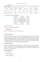
Page 5: ...S232 cable X 1 Remote control transmitter optional X 1 1 2 Tech specifications Parameter Types Items Values Mechanical specifications L W H mm 930 X 699 X 348 Wheelbase mm 498 Front rear wheel base mm...

Page 6: ...brief introduction to the SCOUT 2 0 mobile robot platform as shown in Figure 2 1 and Figure 2 2 Figure 2 1 Front View Figure 2 2 Rear View Stop Switch Figure 2 1 Front View Top Compartment Rear Panel...

Page 7: ...Status indication Users can identify the status of vehicle body through the voltmeter the beeper and lights mounted on SCOUT 2 0 For details please refer to Table 2 1 Status Description Voltage The cu...

Page 8: ...cified threshold voltage Therefore users need to notice that SCOUT 2 0 platform will send a low voltage alarm before the threshold voltage is reached and also pay attention to battery recharging durin...

Page 9: ...es the same CAN communication interface and 24V power interface with the top one two of them are internally inter connected The pin definitions are given in Figure 2 7 Pin No Pin Type Function and Def...

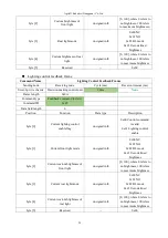
Page 10: ...r velocity commands two switches are enabled by default SWB for control mode selection top position for command control mode and the middle position for remote control mode SWC for lighting control Th...

Page 11: ...onvenience Meanwhile another lighting control interface is reserved on the RC transmitter for energy saving Currently the lighting control is only supported with the FS transmitter and support for oth...

Page 12: ...rect battery voltage and front and rear lights will be both switched on Check the battery voltage If there is no continuous beep beep beep sound from beeper it means the battery voltage is correct if...

Page 13: ...chassis status information in real time The protocol includes system status feedback frame movement control feedback frame and control frame the contents of which are shown as follows The system statu...

Page 14: ...ure bit 2 No 1 motor communication failure 0 No failure 1 Failure bit 3 No 2 motor communication failure 0 No failure 1 Failure bit 4 No 3 motor communication failure 0 No failure 1 Failure bit 5 No 4...

Page 15: ...ode Receiving node ID Cycle ms Receive timeout ms Steer by wire chassis Decision making control unit 0x131 20ms None Data length 0x08 Position Function Data type Description byte 0 Moving speed higher...

Page 16: ...nd control mode which means the chassis can be directly controlled via command However even though the chassis is in command control mode the control mode in the command needs to be set to 0x01 for su...

Page 17: ...rmation will be fed back what s more the information about motor current encoder and temperature are also included The following feedback frame contains the information about motor current encoder and...

Page 18: ...ID Cycle ms Receive timeout ms Steer by wire chassis Decision making control unit 0x201 20ms None Data length 0x08 Position Function Data type Description byte 0 No 2 drive current higher 8 bits unsig...

Page 19: ...loops which will be added once every command sent byte 7 Parity bit checksum unsigned int8 Parity bit Table 3 8 No 4 Motor Information Feedback Command Name No 4 Motor Drive Information Feedback Fram...

Page 20: ...X Robotics Dongguan Co Ltd 19 temperature 1 byte 6 Count parity bit count unsigned int8 0 255 counting loops which will be added once every command sent byte 7 Parity bit checksum unsigned int8 Parity...

Page 21: ...ar light mode unsigned int8 0x00 NC 0x01 NO 0x02 BL mode 0x03 User defined brightness byte 4 Customize brightness for rear light unsigned int8 0 100 where 0 refers to no brightness 100 refers to maxim...

Page 22: ...ts checksum is calculated as follows checksum ID_H ID_L data_length can_msg data 0 can_msg data 1 can_msg data 2 can_msg data 3 can_msg data 4 can_msg data n 0xFF ID_H and ID_L are respectively higher...

Page 23: ...from CAN interface and the host can also parse the current state of chassis with the real time data fed back from CAN bus For the detailed content of protocol please refer to CAN communication protoco...

Page 24: ...d frame ID and checksum composition Where the frame length refers to the length excluding start bit and checksum composition the checksum refers to the sum from start bit to all data of frame ID the f...

Page 25: ...e X 10 with an accuracy of 0 1V byte 3 Battery voltage lower 8 bits byte 4 Failure information higher 8 bits unsigned int16 See notes for details byte 5 Failure information lower 8 bits Description of...

Page 26: ...re decreases and the over current alarm will be actively cleared once the current value is restored to normal condition 3 The over temperature protection of motor drive and the motor over current prot...

Page 27: ...ed percentage signed int8 Maximum speed 0 7853rad s value range 100 100 byte 4 Reserved 0x00 byte 5 Reserved 0x00 No 1 motor drive information feedback frame Command Name No 1 Motor Drive Information...

Page 28: ...drive rotational speed lower 8 bits byte 4 No 2 hard disk drive HDD temperature signed int8 Actual temperature with an accuracy of 1 byte 5 Reserved 0x00 No 3 motor drive information feedback frame Co...

Page 29: ...bits byte 2 No 4 drive rotational speed higher 8 bits signed int16 Actual motor shaft velocity RPM byte 3 No 4 drive rotational speed lower 8 bits byte 4 No 4 hard disk drive HDD temperature signed i...

Page 30: ...aking control unit 20ms None Frame length 0x0A Command type Feedback command 0xAA Command ID 0x07 Data field length 6 Position Function Data type Description byte 0 Current lighting control enable fla...

Page 31: ...B to RS232 serial cable from our communication tool kit to connect it onto the serial port at the rear end Then use the serial port tool to set corresponding baud rate and conduct the test with the ex...

Page 32: ...the waiting time is more than 6s it will enter the application if the connection succeeds connected successfully will be prompted in the text box Load Bin file Click the Upgrade button and wait for t...

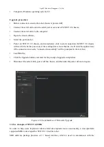
Page 33: ...is best supported in Ubuntu Preparation for development Hardware preparation CANable can communication module X 1 Thinkpad E470 laptop computer X 1 AGILEX SCOUT 2 0 mobile robot chassis X 1 AGILEX SCO...

Page 34: ...s github com westonrobot SCOUT 2 0_ros git cd catkin_make Reference source https github com westonrobot SCOUT 2 0_ros Hardware connection and preparation Lead out CAN cable from SCOUT 2 0 top or rear...

Page 35: ...then stored in full voltage state Please do not put the battery in fire or heat up the battery and please do not store the battery in high temperature environment Charging The battery must be charged...

Page 36: ...tensions involve the storage of important data and have no power off protection 4 4 Mechanical load 4 5 Other notes SCOUT 2 0 has plastic parts in front and rear please do not directly hit those parts...

Page 37: ...ration how to deal with this problem A If SCOUT 2 0 gives this beep beep beep sound continuously it means the battery is in the alarm voltage state Please charge the battery in time Once other related...

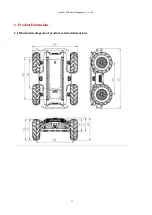
Page 38: ...AgileX Robotics Dongguan Co Ltd 37 6 Product Dimensions 6 1 Illustration diagram of product external dimensions...

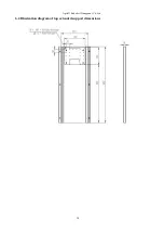
Page 39: ...AgileX Robotics Dongguan Co Ltd 38 6 2 Illustration diagram of top extended support dimensions...

Reviews: