


Hints and Tips
7
Transmission Test Set Quick Reference Guide
73
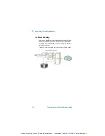
Avoiding Optical Receiver Overload
Check when connecting an optical transmitter to an optical
receiver that you do not overload the receiver. This applies to
elements under test and also the instrument receiver input
ports.
On the instrument connector panel the following output/input
power level information is printed:
When performing tests, it is recommended that you drive the
optical receiver with a signal that has an average power in the
middle of the receiver’s operating range (mid-way between the
upper and lower levels printed next to the Optical In port).
Tx Optical Out
ports:
Maximum available output power
(color - black).
Rx Optical In ports:
Maximum input power (damage
level) the receiver input can accept
before damage occurs
(color - yellow).
Recommended input power operat-
ing range for signals applied to the
receiver (color - green).
Artisan Technology Group - Quality Instrumentation ... Guaranteed | (888) 88-SOURCE | www.artisantg.com


