


Inverted Magnetron Pirani Gauge FRG-700 FRG-702
23
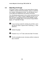
4
Operation
When the supply voltage is applied, the measuring signal is
available between pins 3 and 5. Over the whole measurement
range, the measuring signal is output as a logarithm of the
pressure (measuring signal vs. pressure
"Technical Data").
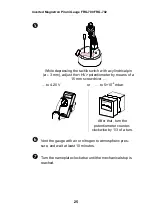
Allow for a stabilizing time of
10 minutes. Once the gauge has
been switched on, permanently leave it on irrespective of the
pressure.
The Pirani measurement circuit is always on.
The cold cathode measurement circuit is controlled by the
Pirani circuit and is activated only at pressures <1×10
-2
mbar.
4.1
Gas Type Dependence
The measurement value depends on the type of gas being
measured. The value displayed is accurate for dry air, O
2
, CO
and N
2
. It can be mathematically converted for other gases
(
"Technical Data").
If the gauge is operated in connection with an Agilent vacuum
gauge controller, a calibration factor can be entered for
correction of the reading.
4.2
Ignition Delay
When cold cathode measurement systems are activated upon
switching the gauge on, an ignition delay occurs, which is
typically:
10
-5
mbar
1 second
10
-7
mbar
20 seconds
5×10
-9
mbar
2 minutes
As long as the cold cathode measurement circuit has not yet
ignited, the measurement value of the Pirani is output as
measuring signal.
Summary of Contents for FRG-700
Page 1: ......
Page 2: ......
Page 3: ...This page is intentionally left blank ...
Page 32: ...Inverted Magnetron Pirani Gauge FRG 700 FRG 702 32 Notes ...
Page 33: ......
Page 34: ......
Page 35: ......
Page 36: ...t q ma 7 4 e 1 ...


