


20
Installation Note E8362-90004
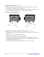
Replace the Bias Tees
(Refer to
1. Remove the old bias tees from the bracket by removing two screws (item
①
) from each.
Retain the screws for installing the new bias tees.
2. Install the new bias tees using the screws (item
①
) removed from the old bias tees. Be sure
to install the ground lug (item
②
) over the attachment screw as shown.
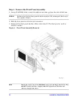
Figure 12 Bias Tees Replacement
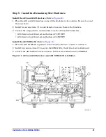
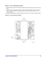
Reinstall the Detector/Bias Tee/Attenuator Brackets
(Refer to
.)
1. Place the brackets, with the attenuators and bias tees attached, into the analyzer as shown
.
2. Reinstall the three screws (item
④
) in each bracket.
3. Reconnect the ribbon cables to the attenuators (item
①
).
4. Reconnect the bias tee control cables to the A16 test set motherboard. The A38 cable
connects to J22 (
P1 BIAS T
) and the A39 cable connects to J25 (
P2 BIAS T
). Be sure to route
them under the cable clamp, (item
③
).
5. Reconnect all RF cables to the attenuators (item
①
) and bias tees (item
②
).


