


Product Information
885
By pressing
Display
>
Data -> Mem
, the contents of the corrected data array
will be copied to this array. The user is allowed to read/write data from/to
the corrected memory array.
Equation Editor
Equation Editor is a function available in Firmware revision A.08.0x or later
that allows users to use a custom equation to display data in the E5071C.
Equation Editor can be accessed through
Display
>
Equation Editor
.
Data Math
Data processing is carried out using the corrected data array and the
corrected memory array. Four types of data processing addition,
subtraction, multiplication, and division are available.
Electrical Delay/Phase Offset
An electrical delay and a phase offset are applied to each trace. By setting
an electrical delay, a linear phase that is proportional to the frequency will
be added or subtracted. On the other hand, setting a phase offset adds or
subtracts a phase that is constant throughout the frequency range.
Incidentally, data processing performed from this point on in the flowchart
is applied to both the data array and the memory array.
TDR Data Array
The results from all data processing done up to this point are stored in this
array. The user is not allowed to access (read/write) this data array.
TDR Memory Array
By pressing Display > Data -> Mem, the contents of the TDR data array
will be copied to this array. The user is not allowed to access (read/write)
this memory array.
Data Format/Group Delay
Complex data consisting of the real parts and the imaginary parts are
converted into scalar data according to the data format of user's choice.
Group delays are also calculated here.
Smoothing
By enabling the smoothing function, each point in a sweep measurement
will be replaced by a moving average of several measurement points
nearby. The number of points used in calculating a moving average is
determined by the smoothing aperture set by the user. The smoothing
aperture is defined by a percentage against the sweep span.
Formatted Data Array/Formatted Memory Array
All results from data processing are stored in the formatted data array and
the formatted memory array. The marker functions are applied to these
Summary of Contents for E5071C
Page 79: ...E5071C 78 ...
Page 87: ...E5071C 86 ...
Page 131: ...E5071C 130 ...
Page 151: ...E5071C 150 4 Click Finish ...
Page 155: ...E5071C 154 Other topics about Calibration with ECal ...
Page 163: ...E5071C 162 ...
Page 167: ...E5071C 166 ...
Page 177: ...E5071C 176 5 The information you entered in Connectors 3 of User Characterization Info screen ...
Page 179: ...E5071C 178 System Selects System ...
Page 186: ...Measurement 185 Transmission Standard Model THRU ...
Page 202: ...Measurement 201 ...
Page 274: ...Measurement 273 frequency band and so on For zero span measurement td2 13 1 µs Typ ...
Page 299: ...E5071C 298 ...
Page 302: ...Measurement 301 5 For more information on displaying the notch search result see Notch Search ...
Page 358: ...Measurement 357 2 port Touchstone file 3 port Touchstone file ...
Page 388: ...Measurement 387 ...
Page 389: ...E5071C 388 ...
Page 402: ...Measurement 401 ...
Page 418: ...Measurement 417 ...
Page 438: ...Measurement 437 ...
Page 469: ...E5071C 468 ...
Page 493: ...E5071C 720 4 Click Finish ...
Page 495: ...E5071C 722 ...
Page 515: ...E5071C 742 ...
Page 575: ...E5071C 802 Center Key Operation Default Value Preset RST Save Recall Maximum Frequency 10E5 2 ...
Page 577: ...E5071C 804 Format Key Operation Default value Preset RST Save Recall Log Mag ...
Page 587: ...E5071C 814 Start Key Operation Default Value Preset RST Save Recall 100 00 kHz ...
Page 599: ...E5071C 826 Security Level Non e ...
Page 615: ...E5071C 842 3 Open the screw in clockwise direction ...
Page 616: ...Product Information 843 4 Press the button under the screw ...
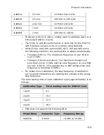
Page 649: ...E5071C 876 N4694A 1 85 mm 10 MHz to 67 GHz ...
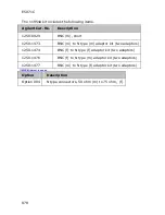
Page 671: ...E5071C 898 At 300 kHz to 1MHz Directivity and Source Match are changed from 25 dB to 20 dB ...
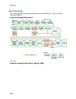
Page 678: ...Product Information 905 E5071C Data Flow ...
Page 684: ...Product Information 911 ...
Page 688: ...Product Information 915 calibration Adapter Removal In sertion calibration ...
Page 694: ...Product Information 921 information ...
Page 709: ...E5071C 936 Parallel port Can be used as a printer or GPIO connector Not available ...
Page 741: ...E5071C 968 ...
Page 751: ...E5071C 978 Example of control using Agilent VEE ...
Page 760: ...Programming 987 5 The E5071C successfully appears in the Instrument Manager 1 ...
Page 767: ...E5071C 994 CALC1 PAR2 SEL CALC1 MARK3 ACT Other topics about Setting up Analyzer ...
Page 849: ...E5071C 1076 Limit Test Limit Test Performing a Limit Test Obtaining Test Results ...
Page 856: ...Programming 1083 ...
Page 866: ...Programming 1093 ...
Page 960: ...Programming 1187 1010 PRINT Done 1020 END IF 1030 SUBEND ...
Page 1044: ...Programming 1271 500 END ...
Page 1083: ...E5071C 1310 familiarity with the E5071C thus minimizing the possibility of human error ...
Page 1274: ...Programming 1501 MsgBox Left Pole LeftStim LeftValue MsgBox Right Pole RightStim RightValue ...
Page 1279: ...E5071C 1506 4 Click Next ...
Page 1280: ...Programming 1507 5 Click Close to complete the installation ...
Page 1285: ...E5071C 1512 8 Notice that ENA TDR connection fails in Agilent Connection Expert main window ...
Page 1288: ...Programming 1515 ...
Page 1380: ...Programming 1607 ...
Page 1493: ...E5071C 1720 10 DIM A 1 201 1 2 20 OUTPUT 717 CALC1 DATA FDAT 30 ENTER 717 A ...
Page 1496: ...Programming 1723 10 DIM A 1 201 1 2 20 OUTPUT 717 CALC1 DATA FMEM 30 ENTER 717 A ...
Page 1537: ...E5071C 1764 10 OUTPUT 717 CALC1 FUNC EXEC ...
Page 1665: ...E5071C 1892 10 DIM B 1 2 1 3 20 OUTPUT 717 CALC1 RLIM REP 30 ENTER 717 A B ...
Page 1695: ...E5071C 1922 10 OUTPUT 717 CONT HAND B 15 20 OUTPUT 717 CONT HAND B DATA 15 ...
Page 1815: ...E5071C 2042 10 OUTPUT 717 CLS ...
Page 1820: ...Programming 2047 10 OUTPUT 717 IDN 20 ENTER 717 A ...
Page 1822: ...Programming 2049 10 OUTPUT 717 OPC ...
Page 1839: ...E5071C 2066 10 DIM A 1000 20 OUTPUT 717 MMEM CAT 30 ENTER 717 A ...
Page 1849: ...E5071C 2076 10 OUTPUT 717 MMEM LOAD CHAN A ...
Page 1861: ...E5071C 2088 10 OUTPUT 717 MMEM LOAD d State01 sta ...
Page 1869: ...E5071C 2096 10 OUTPUT 717 MMEM STOR CHAN A ...
Page 1949: ...E5071C 2176 10 OUTPUT 717 SENS1 CORR COLL LOAD 1 20 OUTPUT 717 OPC 30 ENTER 717 A ...
Page 1953: ...E5071C 2180 10 OUTPUT 717 SENS1 CORR COLL OLO LOAD CLE 1 30 ENTER 717 A ...
Page 1957: ...E5071C 2184 10 OUTPUT 717 SENS1 CORR COLL OLO LOAD DONE 1 20 OUTPUT 717 OPC 30 ENTER 717 A ...
Page 2147: ...E5071C 2374 10 OUTPUT 717 SENS1 CORR OFFS COLL ECAL SOLT1 2 20 OUTPUT 717 OPC 30 ENTER 717 A ...
Page 2217: ...E5071C 2444 10 OUTPUT 717 SENS1 MULT1 PORT1 A 20 OUTPUT 717 SENS1 MULT1 PORT1 30 ENTER 717 A ...
Page 2233: ...E5071C 2460 10 DIM A 1 201 20 OUTPUT 717 SENS1 OFFS LOC DATA 30 ENTER 717 A ...
Page 2253: ...E5071C 2480 10 DIM A 1 201 20 OUTPUT 717 SENS1 OFFS PORT2 DATA 30 ENTER 717 A ...
Page 2359: ...E5071C 2586 10 OUTPUT 717 SOUR POW PORT CORR COLL TABL BSEN DATA 0 Clear Table ...
Page 2502: ...Programming 2729 10 OUTPUT 717 SYSTem COMMunicate USB PMETer CATalog 20 ENTER 717 A ...
Page 2522: ...Programming 2749 10 OUTPUT 717 SYST SERV 30 ENTER 717 A ...
Page 2590: ...Programming 2817 Right click on the time domain active trace and select Switch Gating State ...
Page 2644: ...Programming 2871 ...
Page 2651: ...E5071C 2878 No equivalent GUI is available ...
Page 2656: ...Controlling Multiport Test Set 2883 4 Click Finish ...
Page 2664: ...Controlling Multiport Test Set 2891 ...
Page 2666: ...Controlling Multiport Test Set 2893 ...
Page 2678: ...Controlling Multiport Test Set 2905 E5092A Control Line ...
Page 2679: ...E5071C 2906 ...


