


Programming
963
•
E5071C
•
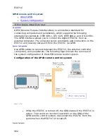
External controller (PC or workstation that can be connected to LAN
and Agilent I/O Library is installed into)
•
Other devices (other instruments and/or peripherals that serve your
purpose)
•
GPIB cables
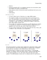
Scale of system you can construct
•
You can connect up to 15 devices in a single GPIB system.
•
The length of cables to connect between devices must be 4 m or
less. The total length of connecting cables in a single GPIB system
must be 2 m × the number of connected devices (including the
controller) or less. You cannot construct the system in which the
total cable length exceeds 20 m.
•
The number of connectors connected to an individual device must be
4 or less. If you connect 5 or more connectors, excessive force is
applied to the connector part, which may result in failure.
•
You can choose the device connection topology from star, linear, and
combined. Loop connection is not supported.
Device selector
The device selector is a unique value assigned to each device that is used
by the controller to select the control target (to send/receive messages)
among devices connected on the GPIB remote control system.
The device selector consists of a select code (usually, 7) and a GPIB
address. For example, when the select code is 7 and the GPIB address is
17, the device selector is 717. The select code must be set for each
system. The GPIB address must be set to a unique value for each device,
Summary of Contents for E5071C
Page 79: ...E5071C 78 ...
Page 87: ...E5071C 86 ...
Page 131: ...E5071C 130 ...
Page 151: ...E5071C 150 4 Click Finish ...
Page 155: ...E5071C 154 Other topics about Calibration with ECal ...
Page 163: ...E5071C 162 ...
Page 167: ...E5071C 166 ...
Page 177: ...E5071C 176 5 The information you entered in Connectors 3 of User Characterization Info screen ...
Page 179: ...E5071C 178 System Selects System ...
Page 186: ...Measurement 185 Transmission Standard Model THRU ...
Page 202: ...Measurement 201 ...
Page 274: ...Measurement 273 frequency band and so on For zero span measurement td2 13 1 µs Typ ...
Page 299: ...E5071C 298 ...
Page 302: ...Measurement 301 5 For more information on displaying the notch search result see Notch Search ...
Page 358: ...Measurement 357 2 port Touchstone file 3 port Touchstone file ...
Page 388: ...Measurement 387 ...
Page 389: ...E5071C 388 ...
Page 402: ...Measurement 401 ...
Page 418: ...Measurement 417 ...
Page 438: ...Measurement 437 ...
Page 469: ...E5071C 468 ...
Page 493: ...E5071C 720 4 Click Finish ...
Page 495: ...E5071C 722 ...
Page 515: ...E5071C 742 ...
Page 575: ...E5071C 802 Center Key Operation Default Value Preset RST Save Recall Maximum Frequency 10E5 2 ...
Page 577: ...E5071C 804 Format Key Operation Default value Preset RST Save Recall Log Mag ...
Page 587: ...E5071C 814 Start Key Operation Default Value Preset RST Save Recall 100 00 kHz ...
Page 599: ...E5071C 826 Security Level Non e ...
Page 615: ...E5071C 842 3 Open the screw in clockwise direction ...
Page 616: ...Product Information 843 4 Press the button under the screw ...
Page 649: ...E5071C 876 N4694A 1 85 mm 10 MHz to 67 GHz ...
Page 671: ...E5071C 898 At 300 kHz to 1MHz Directivity and Source Match are changed from 25 dB to 20 dB ...
Page 678: ...Product Information 905 E5071C Data Flow ...
Page 684: ...Product Information 911 ...
Page 688: ...Product Information 915 calibration Adapter Removal In sertion calibration ...
Page 694: ...Product Information 921 information ...
Page 709: ...E5071C 936 Parallel port Can be used as a printer or GPIO connector Not available ...
Page 741: ...E5071C 968 ...
Page 751: ...E5071C 978 Example of control using Agilent VEE ...
Page 760: ...Programming 987 5 The E5071C successfully appears in the Instrument Manager 1 ...
Page 767: ...E5071C 994 CALC1 PAR2 SEL CALC1 MARK3 ACT Other topics about Setting up Analyzer ...
Page 849: ...E5071C 1076 Limit Test Limit Test Performing a Limit Test Obtaining Test Results ...
Page 856: ...Programming 1083 ...
Page 866: ...Programming 1093 ...
Page 960: ...Programming 1187 1010 PRINT Done 1020 END IF 1030 SUBEND ...
Page 1044: ...Programming 1271 500 END ...
Page 1083: ...E5071C 1310 familiarity with the E5071C thus minimizing the possibility of human error ...
Page 1274: ...Programming 1501 MsgBox Left Pole LeftStim LeftValue MsgBox Right Pole RightStim RightValue ...
Page 1279: ...E5071C 1506 4 Click Next ...
Page 1280: ...Programming 1507 5 Click Close to complete the installation ...
Page 1285: ...E5071C 1512 8 Notice that ENA TDR connection fails in Agilent Connection Expert main window ...
Page 1288: ...Programming 1515 ...
Page 1380: ...Programming 1607 ...
Page 1493: ...E5071C 1720 10 DIM A 1 201 1 2 20 OUTPUT 717 CALC1 DATA FDAT 30 ENTER 717 A ...
Page 1496: ...Programming 1723 10 DIM A 1 201 1 2 20 OUTPUT 717 CALC1 DATA FMEM 30 ENTER 717 A ...
Page 1537: ...E5071C 1764 10 OUTPUT 717 CALC1 FUNC EXEC ...
Page 1665: ...E5071C 1892 10 DIM B 1 2 1 3 20 OUTPUT 717 CALC1 RLIM REP 30 ENTER 717 A B ...
Page 1695: ...E5071C 1922 10 OUTPUT 717 CONT HAND B 15 20 OUTPUT 717 CONT HAND B DATA 15 ...
Page 1815: ...E5071C 2042 10 OUTPUT 717 CLS ...
Page 1820: ...Programming 2047 10 OUTPUT 717 IDN 20 ENTER 717 A ...
Page 1822: ...Programming 2049 10 OUTPUT 717 OPC ...
Page 1839: ...E5071C 2066 10 DIM A 1000 20 OUTPUT 717 MMEM CAT 30 ENTER 717 A ...
Page 1849: ...E5071C 2076 10 OUTPUT 717 MMEM LOAD CHAN A ...
Page 1861: ...E5071C 2088 10 OUTPUT 717 MMEM LOAD d State01 sta ...
Page 1869: ...E5071C 2096 10 OUTPUT 717 MMEM STOR CHAN A ...
Page 1949: ...E5071C 2176 10 OUTPUT 717 SENS1 CORR COLL LOAD 1 20 OUTPUT 717 OPC 30 ENTER 717 A ...
Page 1953: ...E5071C 2180 10 OUTPUT 717 SENS1 CORR COLL OLO LOAD CLE 1 30 ENTER 717 A ...
Page 1957: ...E5071C 2184 10 OUTPUT 717 SENS1 CORR COLL OLO LOAD DONE 1 20 OUTPUT 717 OPC 30 ENTER 717 A ...
Page 2147: ...E5071C 2374 10 OUTPUT 717 SENS1 CORR OFFS COLL ECAL SOLT1 2 20 OUTPUT 717 OPC 30 ENTER 717 A ...
Page 2217: ...E5071C 2444 10 OUTPUT 717 SENS1 MULT1 PORT1 A 20 OUTPUT 717 SENS1 MULT1 PORT1 30 ENTER 717 A ...
Page 2233: ...E5071C 2460 10 DIM A 1 201 20 OUTPUT 717 SENS1 OFFS LOC DATA 30 ENTER 717 A ...
Page 2253: ...E5071C 2480 10 DIM A 1 201 20 OUTPUT 717 SENS1 OFFS PORT2 DATA 30 ENTER 717 A ...
Page 2359: ...E5071C 2586 10 OUTPUT 717 SOUR POW PORT CORR COLL TABL BSEN DATA 0 Clear Table ...
Page 2502: ...Programming 2729 10 OUTPUT 717 SYSTem COMMunicate USB PMETer CATalog 20 ENTER 717 A ...
Page 2522: ...Programming 2749 10 OUTPUT 717 SYST SERV 30 ENTER 717 A ...
Page 2590: ...Programming 2817 Right click on the time domain active trace and select Switch Gating State ...
Page 2644: ...Programming 2871 ...
Page 2651: ...E5071C 2878 No equivalent GUI is available ...
Page 2656: ...Controlling Multiport Test Set 2883 4 Click Finish ...
Page 2664: ...Controlling Multiport Test Set 2891 ...
Page 2666: ...Controlling Multiport Test Set 2893 ...
Page 2678: ...Controlling Multiport Test Set 2905 E5092A Control Line ...
Page 2679: ...E5071C 2906 ...


