


56
Chapter 3
Quick Start Guide
Measurement Example of a Bandpass Filter
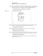
Step 5.
Connect the THRU standard (included in the calibration kit) betwween the measurement
cables as shown in Figure 3-14, and measure the thru calibration data. After measuring the
thru calibration data, symbol
√
is displayed to the left of the
Port 1-2 Thru
button.
•
[Cal] - Calibrate - 2-Port Cal - Transmission - Port 1-2 Thru
Figure 3-14
Connecting the THRU standard
Step 6.
Make the full 2-port calibration measurement DONE. The calibration factor is calculated
based on the calibration data acquired, and the error correction is turned ON.
•
[Cal] - Calibrate - 2-Port Cal - Done
Step 7.
Select the type in which the data is to be saved before saving the calibration factor
(calculated based on the calibration data).
•
[Save/Recall] - Save Type - State & Cal
Step 8.
Store the calibration file to the disk of the E5070B/E5071B. The symbol “X” appearing in
the operations below represent the assigned numbers to be used when the file is saved.
•
[Save/Recall] - Save State - State 0X
For more information on saving/reading internal data, see Chapter “Data Output“ in the
E5070B/E5071B User’s Guide
.


