background image

93

Chapter 4  Features and Functions

Scanning

4

4

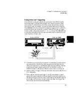
Using External Triggering

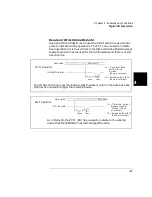
Two control lines are provided in the rear panel mini-DIN connector: 
external trigger in and external trigger out. These lines can be used 
individually or combined to synchronize a scan list with an external 
instrument (such as a DMM). The figure below shows this connection. 
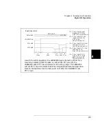
The 3499A/B/C can be configured to output a trigger pulse to notify the 
external instrument whenever a channel is closed. The arm or trigger 
source is then configured as either 

EXT

 or 

MIX 

so that the 3499A/B/C can 

receive the notification from the external instrument to advance to the 
next channel in the scan list.

In addition to the Ext.Trig.In and Ext.Trig.Out pair provided on the 
rear panel of the mainframe, the EI (external increment) and CC 
(channel closed) pair on a 44474A module (see page 248) can also be 
used to synchronize. Specify either Slot 0 or the slot in which a 
44474A module is installed to indicate which lines are to be used.

Both the built-in trigger lines and the EI/CC lines on the 44474A are 
TTL compatible.

Once enabled, the selected trigger-in line is immediately ready to 
accept the trigger signal from the external instrument. Enabling or 
disabling a trigger source from the front-panel sets both the trigger in 
and trigger out functions. On the remote interface, the trigger out 
function can be controlled independently. 

2

3

5

6

8

VM Complete Out

Ext Trig In

(Ext.Trig.Out)

7

(Ext.Trig.In)

Agilent 3499B

External DMM

1

4

Summary of Contents for Agilent 3499A

Page 1: ...em User s Guide Copyright Agilent Technologies Inc 2000 2002 For Safety information Warranties and Regulatory information see the pages following the Index Advanced Test Equipment Rentals www atecorp com 800 404 ATEC 2832 Established 1981 ...

Page 2: ...er interface GPIB IEEE 488 or RS 232 interface control External triggering capability Built in 4 bit digital I O port Store and recall up to 50 customized instrument setups SCPI Standard Commands for Programmable Instruments compatibility Relay cycle count information for preventive maintenance Downloadable firmware upgrades Agilent 3499A Features Five plug in slots Full rack width Agilent 3499B F...

Page 3: ... Module Matrix Modules N2262A 4 x 8 Matrix Module 44473A 4 x 4 Matrix Module High Frequency Switching Modules N2268A 50Ω 3 5GHz Dual 4 to 1 MUX Module N2272A 1 GHz RF 1 to 9 MUX Module N2276A B Dual 1 to 6 4 Microwave MUX Attenuator Module 44472A Dual 4 Channel VHF Switch Module 44478A B 50Ω 75Ω 1 3 GHz Multiplexer 44476A 3 Channel 18 GHz Switch Module 44476B 2 Channel Microwave Switch Module Opti...

Page 4: ...ve identical functionality 1 Power On Standby 8 Scan Keys see page 85 2 Reset Module Instrument 9 Main Menu 3 Shift Local 10 Open Close Relay Channels 4 Store Recall Instrument State 11 Enter a Value Confirm Selection 5 Monitor Channel Port Module 12 Read Write Digital I O Ports 6 View Menu 13 Knob 7 Mode Menu 14 Navigation Arrow Keys ...

Page 5: ...tes of the instrument operation The annunciators are summarized below Other annunciators in the display are not used in the Agilent 3499A B C system Channel Slot Number Annunciators Annunciator Indication SCAN Scan is initiated MON Instrument is in monitor mode VIEW Scan list errors or relay cycle counts are being viewed CONFIG Any configuration key has been pressed Instrument is advancing a scan ...

Page 6: ...panel The figure below shows the Agilent 3499B rear panel Slot 4 Slot 5 Slot 1 Slot 2 Slot 3 GPIB Connector RS 232 Connector Mini DIN Connector Power Input Slot 0 Control Module Slot 1 Slot 2 GPIB Connector RS 232 Connector Mini DIN Connector Power Input Slot 0 Control Module ...

Page 7: ...rear panel mini DIN connector is used to make connections to external triggers and the built in digital I O port An Agilent N2289A cable mini DIN to D9 can be ordered to assist connections to external devices The figure below shows the pins used in the mini DIN connector GPIB Connector RS 232 Connector Mini DIN Connector Power Input Slot 1 Slot 2 Slot 3 Slot 4 Slot 5 Slot 6 Slot 7 2 slot width Slo...

Page 8: ...terface Error Messages Chapter 6 lists the error messages that may appear as you are working with the instrument Plug in Modules Chapter 7 gives detailed information for each plug in module Each module and its wiring is described Additionally wiring information for terminal blocks crimp and insert connections BNC and SMA connections and special cables is included Application Programs Chapter 8 con...

Page 9: ...strument Errors 36 Scanning Operation 38 To Pair Two Modules Together 41 To Configure for External Trigger 42 To Configure the Power on State 44 To Configure the Remote Interface 46 To Perform a Self test 51 To Query the Firmware Revision 52 To Query the Serial Number 53 Local Remote Control 54 Chapter 3 System Overview 55 Agilent 3499A B C Switch Control System 57 Mainframes Overview 58 Firmware ...

Page 10: ...elect the System Mode 112 Chapter 5 Remote Interface Reference 113 SCPI Command Syntax 115 3499A B C SCPI Alphabetical Reference 116 3499A B C SCPI Commands Functionally Grouped 122 Switch Commands 127 Specific Plug in Module Commands 129 Scanning Commands 132 Digital I O Commands 139 State Storage Commands 147 Status System Commands 148 System Information Commands 153 System Level Control Command...

Page 11: ...Quadruple 1 to 2 Optical Switch Module 225 N2281A Dual 1 to 4 Optical Switch Module 226 N2282A 1 to 8 Optical Switch Module 228 44470A 10 Channel MUX Module 230 44470D 20 Channel MUX Module 233 44471A 10 Channel GP Relay Module 236 44471D 20 Channel GP Relay Module 239 44472A Dual 4 Channel VHF Switch Module 242 44473A 4 x 4 2 Wire Matrix Switch Module 245 44474A 16 Bit Digital I O Module 248 4447...

Page 12: ...e 323 N2276A Dual 1 to 6 4 Microwave MUX Attenuator Module 325 N2276B Microwave MUX Attenuator Module 325 N2280A Quadruple 1 to 2 Optical Switch Module 326 N2281A Dual 1 to 4 Optical Switch Module 327 N2282A 1 to 8 Optical Switch Module 328 44470A 10 Channel MUX Module 329 44470D 20 Channel MUX Module 331 44471A 10 Channel GP Relay Module 333 44471D 20 Channel GP Relay Module 335 44472A Dual 4 Cha...

Page 13: ...1 1 Quick Start ...

Page 14: ...me and mount the mainframe onto a system rack The basic operations of the Agilent 3499A B C Switch Control System is also described The chapter contents include To Prepare the Instrument for Use on page 15 To Install a Module in the 3499A B C on page 17 Basic Operation on page 19 To Rack Mount the 3499A B C on page 23 ...

Page 15: ...Connect the 3499A B C to an AC power source with the supplied power cord 2 Push the Power switch located on the lower left side of the front panel 3 On power up every segment in the display will light up briefly including all annunciators Following this starburst display the internal self test will begin 4 If the self test passes1 the default system mode and the GPIB address are displayed together...

Page 16: ...ch control system If the Instrument Does Not Turn On 1 Verify that the power cord is firmly plugged into the power receptacle on the rear panel of the 3499A B C 2 Make sure that the power source the 3499A B C is plugged into is energized 3 Verify that the 3499A B C is turned on Note If the 3499A B C DOES NOT turn on after you perform the above procedure contact your nearest Agilent Service Center ...

Page 17: ...i static procedures when configuring installing or removing any plug in modules To prevent contamination to the modules that could degrade performance handle the modules by the side edges or shields only Do not touch the board surfaces or components Each plug in module may have terminal block s and or the cables for wiring to external circuits These terminations are also shipped separately For mor...

Page 18: ...the instrument 3 Push firmly until the module snaps into place 4 Push both plastic levers inward to lock the module 1 Face the mainframe rear panel toward you 2 Select a slot in which the module is to be installed 1 Wire the screw terminal block module dependent refer to chapter 7 for details 2 Attach the screw terminal block to the plug in module 1 Push firmly until the terminal block snaps into ...

Page 19: ...ent refer to the Remote Interface Reference chapter on page 113 Channel Addressing A channel refers to an individual relay on a switching module or an individual bit port on a digital I O module The channel address is in the form of snn where s represents slot number and nn represents a channel number For all mainframes slot 0 refers to the 3499 controller board Valid slot numbers are The channel ...

Page 20: ...built in digital I O ports The DIN indicates the port is set for a digital input operation As the knob is turned the additional ports are displayed followed by any installed plug in modules If you have installed one or more plug in modules you can select the module by pressing the right arrow key For example if an N2260A 40 channel MUX module is installed in slot 1 pressing the right arrow key wil...

Page 21: ...ed in slot 1 select channel 00 as described on the previous page Press the CLOSE key to close the channel Press the OPEN key to open the channel In this manner you can select and control as many channels as you need The N2260A has 40 channels numbered 0 through 39 in slot 1 100 through 139 You may also select additional plug in modules and channels by turning the knob MUX 100 OPEN MUX 100 CLOSED M...

Page 22: ... the module in slot 1 using the N2260A as an example to show a display similar to this Press and hold the card reset key When you first press the key the display shows When the card has been reset the display briefly shows and then returns to To Reset All Modules You can reset all channels on all modules in the mainframe at once Press the shift key and then press and hold the reset key The display...

Page 23: ... with the optional rack mounting kits The instructions and mounting hardware are included with each rack mounting kit Agilent 3499A To rack mount a 3499A the full rack width mainframe order either Rack mount kit with handles part number 5183 7170 or Rack mount kit without handles part number 5183 7171 To Rack Mount an Agilent 3499A 3499A SWITCH CONTROL SYSTEM ...

Page 24: ...er 5183 7172 includes the flange and filler panel To Rack Mount a Single Agilent 3499B with Adapter kit 5183 7172 OR A Support Shelf part number 5063 9255 A slide kit part number 1494 0015 And a filler panel part number 5002 3999 To Rack Mount a Single Agilent 3499B on a support shelf 3499B SWITCH CONTROL SYSTEM Flange Filler Panel ...

Page 25: ... 3499A B C 4 1 To rack mount two Agilent 3499B s side by side or any System II instrument next to an Agilent 3499B order A Support Shelf part number 5063 9255 And a slide kit part number 1494 0015 To Rack Mount Two Agilent 3499B s Side by side ...

Page 26: ...t handles part number 5063 9216 or Adapter kit with handles part number 5063 9223 To Rack Mount an Agilent 3499C Filler Panels Order filler panels to cover any unused slots in an Agilent 3499A B C 1 slot filler panel part number 03499 00023 option FP1 2 slot filler panel part number 03499 00024 option FP2 Adapter kit ...

Page 27: ...2 2 Front Panel Operation ...

Page 28: ...Errors on page 36 Scanning Operation on page 38 To Pair Two Modules Together on page 41 To Configure for External Trigger on page 42 To Configure the Power on State on page 44 To Configure the Remote Interface on page 46 To Perform a Self test on page 51 To Query the Firmware Revision on page 52 To Query the Serial Number on page 53 Local Remote Control on page 54 The following conventions are use...

Page 29: ...onitoring state 2 Select the slot or the channel port to be monitored The displayed information depends on the selected module type Typical displays are shown in the table on page 81 3 If only part of the channel status on the module can be displayed at one time press Enter to display the next part For multiplexer modules and GP Relay modules 10 channels can be displayed at one time for matrix mod...

Page 30: ...one to this value the H 8 bit port address is obtained Data with a trailing decimal point indicates that the last operation on that port was a WRITE data without a trailing decimal point indicates that the last operation on that port was a READ This display shows that the data last read from Port 401 is 255 and the data last written to Port 400 is 254 The top display is for the built in digital I ...

Page 31: ...it by selecting the channel for example the first bit in the built in port is channel 091 Perform the following procedure to read from a port 1 Select a digital I O port Use the knob to select the slot and channel number The channel number is in the form of snn where s is the slot number and nn is the channel number 2 Read the data read from the selected port For example the display below shows th...

Page 32: ...s a READ and DOUT a WRITE 2 Press the Write key DOUT is displayed to indicate the port is now an output port The current port value is displayed 3 Edit the value Use the arrow keys to select the to be edited bit the digit to be edited is set to half bright in the display Turn the knob to modify the value Use the arrow keys to select the next digit and the knob to modify its value 4 When the value ...

Page 33: ... port level see page 34 The following procedure configures a plug in digital I O module to use a two line digital handshake mode mode 5 for data transfers 1 Select the slot in which a digital I O or multifunction module is installed The channel number is in the form of snn where s is the slot number and nn is the channel number 2 Press the Mode key The CONFIG annunciator lights up in the display a...

Page 34: ...can configure an individual digital I O port to change the data polarity and the display format The following procedure changes the built in digital I O port to display in binary number format 1 Select a digital I O port i e port 090 The channel number is in the form of snn where s is the slot number and nn is the channel number 2 Press the Mode key The CONFIG annunciator lights up in the display ...

Page 35: ...Y is displayed 6 Press Enter to make the change and return to the first level of the Mode menu 7 Press Mode again to exit the current configuration the CONFIG annunciator turns off Note Once you have selected the data display format for a port it applies to both input and output operations on that port BINARY 090 DISP FORMAT 401 ...

Page 36: ...he queue is empty and the ERROR annunciator turns off To view instrument errors 1 Press the View key The VIEW annunciator lights up and the display shows the first menu level 2 Press Enter to view the first error a If no error is in the error queue the ERROR annunciator is off the display shows NO ERROR and then automatically returns to the first level of the View menu b If there are errors the ER...

Page 37: ...ter to return to the first level of the View menu the ERROR annunciator turns off 5 Press View again to exit the View menu operation the VIEW annunciator turns off Note All errors are cleared and the ERROR annunciator turns off once the error queue is viewed See the Error Messages chapter on page 165 for a complete list of error messages ...

Page 38: ...the scan list to control the scan process All these can be done from the S List menu The procedure in this chapter describes a simple scan from the front panel For more information about scanning and using the parameters to control a scan see page 85 To Create a Scan List 1 Press the S List key to enter the scan list menu The CONFIG annunciator lights up and the first level of the menu is displaye...

Page 39: ...el and close the next channel in the list This procedure shows a simple way to scan one channel at a time for each press of a front panel key You can also press the Scan key to scan all channels in the list according to the various scan parameters set In the default parameter state pressing the Scan key will cause all the channels in the list to cycle through at the maximum possible speed While th...

Page 40: ...annunciator lights up and the display shows the first level menu 2 Turn the knob until SCAN LIST is displayed 3 Press Enter The first channel in the scan list is displayed on the channel area Turn the knob to view other channels in the scan list 4 Press Enter to return to the first level of the View menu 5 Press View again to exit the View menu The VIEW annunciator turns off ERROR 101 SCAN LIST 10...

Page 41: ...duplicated on the corresponding channel of the other module The example below pairs modules installed in slots 2 and 5 1 Press the Menu key The CONFIG annunciator lights up and CARD PAIR is displayed 2 Press Enter When FIRST SLOT x is displayed turn the knob to select the first slot to be paired i e Slot 2 3 Press Enter When SECOND SLOT x is displayed turn the knob to select the second slot to be ...

Page 42: ...losed pair on a 44474A module Only one pair can be used at a time You can specify which pair to use and whether a trigger out pulse is sent out when a relay is closed during scanning operations Refer to Scanning on page 85 for more details 1 Press the Menu key The CONFIG annunciator lights up and the display shows the first level menu 2 Turn the knob to show the second menu item CONF EXT TRIG 3 Pr...

Page 43: ...ble at the rear panel mini DIN connector see page 7 If a 44474A is not installed only slot 0 will be shown Press Enter The display shows the current setting for the external trigger 5 Turn the knob to show the alternate choice 6 Press Enter to accept the choice and return to the first level menu 7 Press the Menu key to exit the menu The CONFIG annunciator turns off DISABLE ENABLE CONF EXT TRIG ...

Page 44: ...usly stored in a specified memory location The instrument will return to the specified state the next time it is turned on 1 Press the Menu key The CONFIG annunciator lights up and the display shows the first menu level 2 Turn the knob until POWER ON SET is displayed 3 Press Enter to show the second level menu 4 To set the instrument power on to the reset state press Enter The instrument will retu...

Page 45: ...to the first level menu More information about storing states is given on page 106 of this manual 8 Press the Menu key again to exit the Menu menu The CONFIG annunciator turns off Note If the instrument is set to power on to a previously stored setup that is no longer valid it will automatically power on to the reset state and RECALL FAILED will be displayed POWER ON 08 POWER ON SET ...

Page 46: ...ry the GPIB interface is selected and its address is set to 9 The GPIB address of the instrument can be set to any value between 0 and 30 The GPIB address is stored in non volatile memory and does not change when the instrument is turned off or reset Switching between SCPI mode and 3488A mode causes the 3499A B C to select the GPIB interface and its address setting To set the GPIB interface 1 Pres...

Page 47: ...ress Enter to show the second parameter 7 Press Enter to enable the instrument to assert the SRQ line when powered up If the computer is so configured this can be used to interrupt the system computer To disable this feature turn the knob to select SRQ OFF and press Enter The instrument returns to the first level of the menu 8 Press Menu again to exit the menu The CONFIG annunciator turns off ADDR...

Page 48: ...ta it continues sending data until the XOFF 13h character is received When the XON character 11h is received the instrument resumes sending data DTR DSR In this mode the instrument monitors the state of the DSR data set ready line on the RS 232 connector When the line goes true the instrument sends data over the interface When the line goes false the instrument stops sending information typically ...

Page 49: ... select INTERFACE in the menu 3 Press Enter to show the second level menu The active interface is shown If necessary turn the knob until RS 232 is displayed 4 Press Enter to select the interface and show the first parameter 5 Turn the knob until the desired baud rate is displayed 6 Press Enter to select the baud rate and show the second parameter CARD PAIR INTERFACE RS 232 9600 BAUD 19200 BAUD NON...

Page 50: ...isplayed 8 Press Enter to select the parity and data bits and show the fourth parameter 9 Turn the knob until the desired mode is displayed 10 Press Enter to select the parity and data bits and return to the first level of the Menu menu 11 Press Menu again to exit the menu The CONFIG annunciator turns off EVEN 7 BITS FLOW NONE FLOW RTS CTS INTERFACE ...

Page 51: ... display will briefly show a starburst pattern all display segments lit Following the pattern the display indicates while the internal tests are being performed The self test takes several seconds to complete If the self test is successful PASSED will be displayed Otherwise the reason of the failure will be displayed For details on self test failures refer to Self Test Errors on page 172 4 Press E...

Page 52: ...e Firmware and Control Module Description on page 59 1 Press the Menu key The CONFIG annunciator lights up and the first level menu is shown 2 Turn the knob to select REVISION INFO 3 Press Enter The system firmware revision number will be displayed 4 Press Enter to return to the first level of the Menu menu 5 Press Menu again to exit the Menu menu the CONFIG annunciator turns off CARD PAIR REVISIO...

Page 53: ...Press the Menu key The CONFIG annunciator lights up and the first level menu is shown 1 Turn the knob to select SERIAL NO 2 Press Enter The Agilent 3499A B C serial number is displayed 3 Press Enter again to return to the first level of the Menu menu 4 Press Menu again to exit the Menu menu the CONFIG annunciator turns off CARD PAIR SERIAL NO MY12345678 SERIAL NO ...

Page 54: ...r the remote interface The RMT annunciator lights You can regain control of the front panel keys when the instrument is in remote by pressing the Shift Local key The RMT annunciator turns off and the instrument return to local mode Note If the front panel keys are locked through either the SYSTem RWLock command on the RS 232 interface or a LOCAL LOCKOUT command on the GPIB interface the local key ...

Page 55: ...3 3 System Overview ...

Page 56: ...or switching and control followed by a description of the three mainframes and all the Plug in modules The following sections are included in this chapter Agilent 3499A B C Switch Control System on page 57 Mainframes Overview on page 58 Firmware and Control Module Description on page 59 Plug in Modules Overview on page 61 Channel and Slot Addressing on page 70 Factory Default and Reset States on p...

Page 57: ...Ms scopes counters power supplies etc Whether you are involved in a large production test system or a small R D bench top system the Agilent 3499A B C provides an ideal combination of price performance solution With a wide variety of available plug in modules you can configure your test system much more easily and flexibly The figure below shows the typical configuration of a test system A Typical...

Page 58: ...he front panel or programed over a remote interface GPIB or RS 232 The mainframes can be operated in either of two system modes SCPI mode or 3488A mode The SCPI mode allows the full realization of performance potentials and advanced features such as parallel operation of multiple relays on multiple modules The 3488A mode is included for backward compatibility with the legacy Agilent 3488A system T...

Page 59: ...el or page 153 for remote interface operation From the front panel From the remote interface in response to the IDN query one of two typical strings is returned Agilent Technologies 3499 cnxxxxxx 3 0 Agilent Technologies 3499 myxxxxxx 4 0 2 0 In these strings cnxxxxxx or myxxxxxx is the instrument serial number Note that the control module revision is not returned for revision 1 0 control modules ...

Page 60: ...272A N2276A B N2282A Firmware Version 2 0 allows programming in both SCPI Mode and 3488A Mode Upgrade to Firmware Revision 3 0 ONLY if using N2272A N2276A B or N2282A 3 0 1 0 Stored setups are cleared if power is cycled SCPI Mode supports all modules 3488A Mode supports all modules except N2272A N2276A B or N2282A Firmware Version 3 0 limits programming to either SCPI Mode or 3488A Mode not both U...

Page 61: ...ifunction modules Optical Modules Note Refer to the Plug in Modules chapter on page 173 for the details of the individual Plug in modules MUX Modules A MUX multiplexer module switches one signal to multiple DUTs devices under test or multiple signals to one device one at a time Example applications include capacitor leakage connector switch contact and insulation resistance test systems To expand ...

Page 62: ...ire multiplexer switches both HI and LO inputs 200 V 1 A with DPST relays It can be configured as an 80 channel 1 wire two independent 20 channel 2 wire or a 20 channel 4 wire MUX module N2266A 40 Channel MUX Module 1 Reed non latching Primarily a 40 channel 2 wire multiplexer In SCPI mode it can be configured as an 80 channel 1 wire two independent 20 channel 2 wire or a 20 channel 4 wire MUX mod...

Page 63: ...Module 1 Latching The 10 20 DPST Double pole Single throw relays switch both HI and LO inputs up to250V 2A with low differential offsets for accurate measurements 44472A Dual 4 Channel VHF Switch Module 1 Latching The two independent groups of bidirectional 1x4 switches with 50Ω characteristic impedance can be used for signals from DC to 300 MHz 44478A B 50Ω 75Ω 1 3 GHz Multiplexer 1 Latching The ...

Page 64: ...lists the available GP relay modules L H CH03 L H CH01 L H CH02 L H CH04 CH03 CH01 CH02 CH04 Model Number Module Name Mainframe Slots Required Relay Type Description N2261A 40 ChannelGP Relay Module 1 Latching The 40 independent SPST relays provide quality connections for low level signals Can also switch signals up to 200V 1A N2267A 8 Channel High Current GP Module 1 Non latching An 8 channel Hig...

Page 65: ...0Ω SPDT Single pole Double throw coaxial switches with SMA connectors provide high isolation low insertion loss and low VSWR for switching signals up to 18 GHz 44476B 2 Channel Microwave Switch Module 1 NA Similar to the 44476A but does not have the coaxial switches installed A variety of coaxial switches can be mounted onto the module to provide 3 4 or 5 port switching up to 26 5 GHz 44477A 7 Cha...

Page 66: ...binations A matrix is arranged in rows and columns and a simple 4 x 4 matrix switch is shown below Matrix Switching The table below lists the available matrix modules Model Number Module Name Mainframe Slots Required Relay Type Description N2262A 4 x 8 Matrix Module 1 Latching Each crosspoint or node of the 4 x 8 matrix module uses a DPST Double pole Single throw relay to switch two wires Hi Lo fo...

Page 67: ...itches A simplified schematic of a single digital input and output line is shown below A Simple Digital I O Circuit The table below lists the available digital I O modules 5V OPEN COLLECTOR CURRENT SINK VMOS FET DRIVER OUTPUT INPUT SENSE REFERENCE VOLTAGE ONE I O LINE Model Number Module Name Mainframe Slots Required Descriptions N2263A 32 Bit Digital I O Module 1 The module offers 32 bidirectiona...

Page 68: ...rix module and a 16 bit digital I O module The table below lists the available multifunction modules Model Number Module Name Mainframe Slots Required Relay Type Description N2264A 12 Channel GP 3 Channel High current GP 16 Bit Digital I O Module 1 Non latching The module provides 12 channel SPST Single pole Single throw GP relays for signals up to 200 V 1 A 3 channel high current GP relays for si...

Page 69: ...ormation about these three optical modules Model Number Module Name Mainframe Slots Required Relay Type Description N2280A Optical Switch Quad 1 to 2 MUX Module 2 Non latching Four 1 to 2 Optical Switches N2281A Optical Switch Dual 1 to 4 MUX Module 2 Non latching Two 1 to 4 Optical Switches N2282A Optical Switch 1 to 8 MUX Module 2 Latching One 1 to 8 Optical Switch ...

Page 70: ...e s00 s01 s78 s79b 2 Wire Mode s00 s01 s38 s39 Dual 2 Wire Mode s00 s01 s38 s39 4 Wire Mode s00 s01 s18 s19c N2261A 40 Channel GP Relay Module s00 s01 s02 s03 s37 s38 s39 N2262A 4X8 Matrix Module Row 0 1 2 3 Column 0 1 2 3 6 7 s00 s01 s02 s07 s10 s11 s12 s17 s20 s21 s22 s27 s30 s31 s32 s37 d a The N2260A and N2266A can be used as an 80 channel 1 wire MUX module a 40 channel 2 wire MUX module two 2...

Page 71: ... 2 Wire Mode s00 s01 s38 s39 Dual 2 Wire Mode s00 s01 s38 s39 4 Wire Mode s00 s01 s18 s19d N2267A 8 Channel High Current GP Module s00 s01 s02 s07 N2268A 50Ω 3 5 GHz Dual 4 to 1 MUX Module s00 s01 s02 s03 s10 s11 s12 s13 a A channel number on a matrix module is formed in Slot Row Column format i e channel address s23 means row 2 column 3 in Slot s b The N2260A and N2266A can be used as an 80 chann...

Page 72: ... N2281A Optical Switch Dual 1 to 4 MUX Module s00 s01 s02 s03 s10 s11 s12 s13 N2282A Optical Switch 1 to 8 MUX Module s00 s01 s02 s07 4 Bit Built in Digital I O slot 0 control module Individual Bits 091 092 093 094 4 Bit Port 090 44470A 10 Channel MUX Module s00 s01 s02 s03 s08 s09 44470D 20 Channel MUX Module s00 s01 s02 s03 s18 s19 44471A 10 Channel GP Relay Module s00 s01 s02 s03 s08 s09 44471D...

Page 73: ...annel 13 GHz Microwave Switch Module s00 s01 s02 44476B 2 Channel 26 GHz Microwave Switch Module s00 s01 44477A 7 Channel Form C Relay Module s00 s01 s02 s03 s04 s05 s06 44478A 50 Ω 1 3 GHz MUX Module Group 0 s00 s01 s02 s03 Group 1 s10 s11 s12 s13 44478B 75 Ω 1 3 GHz MUX Module Group 0 s00 s01 s02 s03 Group 1 s10 s11 s12 s13 a A channel number on a matrix module is formed in Slot Row Column forma...

Page 74: ...as well as the default settings when the instrument is shipped from the factory A table showing the 3488 reset settings is given on page 76 You can reset the instrument either by pressing Shift Card Reset on the front panel or with a RST command over the remote interface If a module is accidentally removed or installed while the instrument power is on the instrument will preform a reset ...

Page 75: ...CPI Mode Keep current setting 3488A Mode Keep current setting System Related Display State On On Stored State Empty Keep current setting Error Queue Empty Not cleared Module Related Switching Channels Open Open Digital I O Ports Input Input Card Pair None None Scan Related Scanning None Stop scan in progress Scan List Empty Empty ARM SOURce IMMediate IMMediate ARM TIMer seconds 0 0 Arm Count 1 1 T...

Page 76: ...ddress 9 Keep current settinga RS 232b Keep current setting System Mode SCPI Mode SCPI Mode Keep current setting 3488A Mode Keep current setting System Related Display State On On Stored State Empty Keep current setting Error Queue Empty Cleared Module Related Switching Channels Open Open Digital I O Ports Input Input Card Pair None None Scan Related Scanning None Stop scan in progress Scan List E...

Page 77: ...4 4 Features and Functions ...

Page 78: ...Parallel Switching on page 84 Scanning on page 85 Digital I O Operation on page 95 State Storage on page 106 Error Conditions on page 108 Self Test on page 109 Display Control on page 110 Relay Cycle Counts on page 111 To Select the System Mode on page 112 The following conventions are used for the front panel operation All keys on the front panel keyboard are expressed in bold font and normally a...

Page 79: ...ter which allows you to specify one or more channels The channel number has the form snn where s is the slot number and nn is the channel number You can specify a slot a single channel multiple channels or a range of channels as described below The following command closes a single channel channel 11 on the module installed in slot 1 ROUT CLOS 111 The following command closes multiple channels on ...

Page 80: ...elect a channel a digital I O port or a slot press Mon The MON annunciator lights up Press Mon again to exit this state If only part of the channel status on the module can be displayed at one time press Enter to display the next part Remote Interface Operation To enable the monitor mode send a SCPI command similar to the ones shown below DIAG MON 103 Monitor Channel 103 DIAG MON 400 Monitor a DIO...

Page 81: ...s Adding one to this value the H 8 bit port address is obtained Data with a trailing decimal point indicates that the last operation on that port was a WRITE data without a trailing decimal point indicates that the last operation on that port was a READ This display shows that the data last read from Port 401 is 255 and the data last written to Port 400 was 254 The top display is for the built in ...

Page 82: ...odule is reset all of the closed relay channels on the module will be opened Whenever the instrument is turned on or reset all of the closed relay channels in the instrument will be opened Front Panel Operation Select a channel press Open or Close Select a slot press and hold Card Reset to open all channels on the selected module Press Shift then press and hold Card Reset to open all channels in t...

Page 83: ...o be an 80 channel 1 wire module only one channel can be closed at a time For more information about the N2260A see page 176 For more information about the N2266A see page 200 Front Panel Operation Select the slot in which an N2260A or N2266A is installed press Mode the CONFIG annunciator lights up Select the desired function mode i e 1 wire mode Press Enter Remote Interface Operation A command pa...

Page 84: ...to 10 in the same bank can be closed simultaneously parallel switching Since a relay is controlled by the signal applied to it s coil relay coils can be arranged in arrays to simplify the driver circuits Coils aligned in the same row share a common row control signal and coils aligned in the same column share a common column control signal The figure below shows an array of coils with 4 rows and 1...

Page 85: ...while the instrument is operating the instrument will automatically perform a reset and the current scan list is cleared If a scan list contains a non existing channel the scan cannot be performed and an error will occur If a scan list contains a channel on a digital I O module that is not configured to handshake mode 1 or mode 2 see page 98 the scan cannot be performed and an error will occur If ...

Page 86: ...proceeds to the trigger layer In the trigger layer for each detected trigger source it advances one step in the scan list After advancing through all the channels bits in the scan list and reaching the arm count the scan is terminated and the instrument returns to the idle state Idle Trigger Event Detection Arm Event Detection Another Scan Another Channel yes no no yes Scan Channel Output Trigger ...

Page 87: ...oceed to the trigger layer unless the specified time interval has elapsed IMM with IMM default arm source selected operation immediately proceeds to the trigger layer as soon as the instrument is taken out of the idle state BUS with bus arm source selected the instrument will not proceed to the trigger layer unless a GET or a TRG command is received or Step on the front panel is pressed EXT with e...

Page 88: ...t trigger source selected the scan list advances as soon as the previous channel is opened BUS with bus trigger source selected the scan list advances when a GET or a TRG command is received or Step on the front panel is pressed EXT with external EXT trigger source selected the scan list advances when an external trigger is received from the specified trigger in line MIX with mix trigger source se...

Page 89: ...t each desired channel and press Enter to add the channel to the scan list As channels are added an asterisk is shown in the display to indicate the channel is a part of the scan list Remote Interface Operation You may use single channels ranges of channel or stored setups in the scan list Set up a scan list with one command as follows ROUTe SCAN 100 104 109 411 1 Create scan list to include chann...

Page 90: ...pecify the number of times between 1 and 99999 the instrument is to sweep through the scan list When the specified number is reached the scan stops You can specify a delay time from 0 to 99999 999 seconds with 1 ms resolution between when a channel is closed and when the next operation begins and if configured a trigger out pulse is sent The delay time can be set individually for each channel in t...

Page 91: ... source to IMM ARM COUNt 10 Set arm count to 10 times TRIGger SOURce TIMer Set trigger source to TIMer TRIGger TIMer 5 Set the trigger timer to 5 seconds ROUTe CHANnel DELAY 2 101 Set a 2 second time delay for channel 101 CONFIG SCAN ARM IMM TRIG IMM 00000 0000 SECS Press S List Turn knob Press Enter Turn the knob to select the arm source Press Enter Use arrow keys and knob to select the delay tim...

Page 92: ...diate the scan will begin when the key is pressed If you have configured other arm or trigger sources the scan will begin when the source criteria are met Stop a scan in progress by pressing Shift Scan The last channel closed in the scan list will remain closed You cannot pause and then continue a scan You must start the scan operation over Press Step to start and step through the channels in the ...

Page 93: ...nnel in the scan list In addition to the Ext Trig In and Ext Trig Out pair provided on the rear panel of the mainframe the EI external increment and CC channel closed pair on a 44474A module see page 248 can also be used to synchronize Specify either Slot 0 or the slot in which a 44474A module is installed to indicate which lines are to be used Both the built in trigger lines and the EI CC lines o...

Page 94: ...gain to exit the menu Press S List select CONFIG SCAN and configure the arm source or trigger source as either EXT or MIX Remote Interface Operation The following code segment will set up the 3499A B C to synchronize with an external instrument CONFigure EXTernal TRIGger SOURce 0 Select to use the built in ext trig in and ext trig out lines CONFigure EXTernal TRIGger OUTPut 1 Enable to output a tr...

Page 95: ...ut or output operation then all other bits of the same port can only be used for the same operation Note For more information about a specific digital I O module refer to Plug in Modules starting on page 173 Digital I O Configuration Parameters such as flow control mode control line polarity PCTL flag line polarity PFLG and I O direction line polarity are all configured for the plug in digital I O...

Page 96: ...ct a digital I O port then press Mode the CONFIG annunciator lights up When DATA POLARITY appears in the display press Enter to set data line polarity and or use the knob to select DISP FORMAT and press Enter to set data display format for the port N2263A 4 CONFIG DIO 4 MODE 1 4 CONT POL POS 4 Select flow control mode Press Enter Select the control line polarity Press Enter Select the flag line po...

Page 97: ...IGital MODE 4 1 Set the flow control mode to Mode 1 SOURce DIGital CONTrol POLarity 4 1 Set the PCTL line polarity to negative SOURce DIGital FLAG POLarity 4 0 Set the PFLG line polarity to positive SOURce DIGital IO POLarity 4 1 Set the I O Direction line polarity to negative Set the data line polarity using the following command SOURce DIGital DATA BYTE POLarity 400 POS Set the data line polarit...

Page 98: ...assumed to be positive the default in the following diagrams and discussions Mode Number Handshake Mode Definition Notes 1 Static mode 1 Default handshake mode 2 Static mode 2 Read what was written 3 Read or Write and strobe If you set a port to this mode you cannot use the port in a scan list or use card pairing ROUTe CPAir 4 Read and write strobe If you set a port to this mode you cannot use the...

Page 99: ...devices might load the lines and cause a false read Timing for the I O direction line is as shown in Mode 1 for write operations For read operations the I O direction line does not change DATA VALID DATA LINES I O DIRECTION t1 I O input to data valid 1m s m inim um t1 1ms Write Operation CLOSE DWRITE etc Approximately 1 ms after the I O direction line goes to a low state the digital I O module tak...

Page 100: ...following diagram DATA VALID DATA LINES I O DIRECTION t1 Tim e from I O line low to output enable Write Operation STROBE PCTL LINE t1 1ms t2 25 µs t3 20 µs 1 m s m inim um t2 Tim e from output enable to start of s trobe 25 µs t3 Strobe pulse width 20 µs m inim um m inim um A Strobe pulse signifies that the data on the data lines is valid During a write operation the device receiving the data is tr...

Page 101: ...DATA VALID DATA LINES W rite Operation IO DIRECTION WR t1 40 µs t2 20 µs t1 Tim e from data valid to write Strobe t2 Strobe pulse width 20 µs m inim um The IO Direction line is used to indicate that the data is valid on the data bus lines IO Direction is used to trigger the receiving device 40 µs m inim um DATA LINES Read Operation PCTL RD LINE t1 100 µs t2 20 µs t1 T im e from output disable to r...

Page 102: ... controls the PCTL RD line DATA VALID DATA LINES I O DIRECTION t1 Tim e from I O line low to check for W rite Operation P FL G low t2 T im e from PF LG low to data valid 40 µs m inim um t3 T im e from data valid to P CT L low PCTL LINE PFLG LINE t1 1 ms t2 40 µs t3 30 µs t4 40 µs t5 35 µs 30 µs m inim um t4 T im e from P CT L low to check for P FL G high 40 µs m inim um t5 T im e from P FL G to P ...

Page 103: ...r P CT L low 50 µs m inim um t4 Tim e from PC TL low to check P FL G high 40 µs m inim um t5 Tim e from PF LG high to P CT L high and data latched 35 µs m inim um 45 µs m inim um As with the Write operation the 3499A B C begins by testing PFLG for a low state indicating that the data is valid When PFLG is low the 3499A B C sets PCTL low and waits for PFLG to go high The 3499A B C will set PCTL hig...

Page 104: ...t Panel Operation Select an 8 bit digital I O port press Read to read the data from the port The data can be displayed as either decimal or binary see page 34 Remote Interface Operation Use the following command to read an individual bit bit 6 on a module in slot 4 A 0 bit cleared or a 1 bit set will be returned SENSe DIGital DATA BIT 406 Read the bit channel 406 The following commands read values...

Page 105: ... Operation Select an 8 bit port press Write the data from the last operation read or write will be displayed Edit the data to the desired value and press Enter to write the data to the port To cancel the write operation press Write again instead of Enter You can edit the data in either binary or decimal form see page 34 Remote Interface Operation The following commands write an individual bit SOUR...

Page 106: ...rmware revision of your 3499A B C see page 59 Firmware revision 1 0 must be upgraded Please contact your nearest Agilent Technologies Office for details Firmware revisions 2 0 and 3 0 allow up to 10 states to be stored Firmware revision 4 0 allows up to 50 stored states Stored states are lost if power is removed for firmware revisions 2 0 and 3 0 Stored states are preserved when power is removed f...

Page 107: ...ore an instrument setup press Shift Recall select a memory location and press Enter To cancel the store operation press Recall again instead of Enter Remote Interface Operation SAV 1 Store an instrument setup in memory location 1 Note Approximately 1 second is required to store an instrument setup into an Agilent 3499A B C with Firmware REV 4 0 To avoid errors in when programming be sure to allow ...

Page 108: ...nds with NO ERROR The error queue will be cleared automatically once you read the queue change the system mode send the CLS command or cycle power on the instrument However a module reset or an instrument reset will not clear the error queue Front Panel Operation Press View select ERROR and press Enter The first error recorded is displayed Use the arrow key to scroll through the entire error messa...

Page 109: ... PASSED will be displayed on the front panel Otherwise the reason of the failure will be displayed For details of all self test failures refer to Self Test Errors on page 172 Front Panel Operation Press Menu use the knob to select SELFTEST and press Enter to perform a self test Remote Interface Operation TST Returns zero if the test is successful or non zero if it fails ...

Page 110: ...cked If the display is turned off pressing Local causes the instrument to return to local operation the display will be turned back on The display is automatically turned on when power is cycled or after a RST command When the display is on you can send a message up to 13 characters to display on the front panel from the remote interface If you attempt to send more than 13 characters only the firs...

Page 111: ...CLES and press Enter Turn the knob to select the relay channel of interest The display shows the channel cycle count Remote Interface Operation Integer values are returned to indicate the cycle count If you request more than one value the integers are returned as comma separated values in the same order as the channel in the query command DIAGnostic RELay CYCLes 101 Query relay cycle count of chan...

Page 112: ...ODE is displayed then press Enter 2 Turn the knob until the desired system mode i e 3488A MODE is displayed then press Enter 3 The instrument will be reset if the system mode has been changed Otherwise it retains the current mode and you can press Menu again to exit this operation Note Switching between SCPI mode and 3488A mode will reset the instrument to the factory default settings except the G...

Page 113: ...5 5 Remote Interface Reference ...

Page 114: ...n page 115 3499A B C SCPI Alphabetical Reference on page 116 3499A B C SCPI Commands Functionally Grouped on page 122 Switch Commands on page 127 Specific Plug in Module Commands on page 129 Scanning Commands on page 132 Digital I O Commands on page 139 State Storage Commands on page 147 Status System Commands on page 148 System Information Commands on page 153 System Level Control Commands on pag...

Page 115: ... which allows you to specify one or more channels The channel number has the form snn where s is the slot number and nn is the channel number You can specify a slot a single channel multiple channels or a range of channels as described below The following command closes a single channel channel 11 on the module installed in slot 1 ROUT CLOS 111 The following command closes multiple channels on mod...

Page 116: ...gger source in ARM layer See page 134 COUNt number MIN MAX Set counter in ARM layer See page 134 COUNt MIN MAX Query counter in ARM layer See page 134 TIMer seconds MIN MAX Set timer for sweep to sweep sweeping See page 135 TIMer Query timer in arm layer See page 135 CONFigure EXTernal TRIGger SOURce number Select the trigger source See page 137 EXTernal TRIGger SOURce Query the trigger source See...

Page 117: ...slot Query maximum cycles of channel relays See page 155 RELay CYCLes CLEar channel_list Clear channel relay cycle See page 155 SPEEK slot register Read a 8 bit data from the register specified See page 131 SPOKE slot register data Write a 8 bit data to the register specified See page 131 INITiate Start a scanning cycle See page 138 ROUTe CHANnel DELay seconds channel_list ALL Set channel to chann...

Page 118: ...age 128 SCAN LIST scan_list Set a sequence of channels to be scanned See page 132 SCAN LIST Query the scan list See page 132 SCAN CLEar Clear the scan list See page 132 SCAN SIZE Query the size of the scan list See page 132 SOURce DIGital MODE slot mode Set the digital I O mode See page 140 MODE slot Query the digital I O mode See page 140 CONTrol POLarity slot polarity Set the polarity of control...

Page 119: ...D VALue port data Write a data to the specified port See page 144 DATA BYTE WORD LWORD BLOCK port block_data Write a block of data to the specified port See page 144 DATA BYTE WORD LWORD TRACE port sys_mem_name Write the data block in system memory to the specified digital I O port See page 145 TRACe DEFine sys_mem_name size fill Define the size of data block See page 145 TRACe DEFine sys_mem_name...

Page 120: ... the specified port to the predefined memory block See page 146 TRACe DATA sys_mem_name Get the data block being read See page 146 STATus OPERation CONDition Query the Operation Condition register See page 150 OPERation ENABle unmask Set the Operation Enable register See page 150 OPERation ENABle Query the Operation Enable register See page 150 OPERation EVENt Query the Operation Event register Se...

Page 121: ...RWLock Lock all keys on the front panel See page 160 STATe DELete 1 10 ALL Clear one or all the previously stored instrument states See page 147 VERSion Query the firmware version of the instrument See page 153 TRIGger IMMediate Software trigger for HOLD off triggering See page 138 SOURce BUS EXTernal IMMediate TIMer MIX HOLD Select trigger source in trigger layer See page 135 SOURce Query trigger...

Page 122: ...formation ROUTe CLOSe channel_list CLOSe channel_list CLOSe STATe OPEN channel_list ALL OPEN channel_list Specific Plug in Commands see page 129 for more information ROUTe CPAir slot1 slot2 1 CPAir FUNCtion slot 1 2 3 4 WIRE1 WIRE2 BIWIRE2 WIRE4 FUNCtion slot DIAGnostic SPEEK slot register SPOKE slot register data Scan List Commands see page 132 for more information ROUTe SCAN LIST scan_list SCAN ...

Page 123: ...URce BUS EXTernal IMMediate TIMer MIX HOLD SOURce TIMer seconds MIN MAX TIMer MIN MAX ROUTe CHANnel DELay seconds channel_list ALL CHANnel DELay channel_list CONFigure EXTernal TRIGger SOURce slot EXTernal TRIGger SOURce EXTernal TRIGger OUTPut 0 1 OFF ON EXTernal TRIGger OUTPut Scanning Commands see page 138 for more information INITiate ABORt TRIGger IMMediate TRG Digital Input Commands see page...

Page 124: ...OS NEG CONTrol POLarity slot FLAG POLarity slot 0 1 POS NEG FLAG POLarity slot IO POLarity slot 0 1 POS NEG IO POLarity slot SOURce DIGital DATA BYTE WORD LWORD POLarity port 0 1 POS NEG BYTE WORD LWORD POLarity port Digital I O Memory Commands see page 145 for more information SOURce DIGital DATA BYTE WORD LWORD TRACe port sys_mem_name SOURce DIGital TRACe DEFine sys_mem_name size fill DEFine sys...

Page 125: ...e mem ALL Status System Commands see page 148 for more information CLS ESE value ESE SRE value SRE STB STATus OPERation CONDition OPERation ENABle unmask OPERation ENABle OPERation EVENt PRESet System Information Commands see page 153 for more information IDN SYSTem CTYPE slot ERRor VERSion DIAGnostic RELay CYCLes channel_list RELay CYCLes MAX slot RELay CYCLes CLEar channel_list ...

Page 126: ...l Commands see page 156 for more information OPC OPC RST TST WAI SYSTem CPON slot ALL DIAGnostic DISPlay INFOrmation message DISPlay STATe 0 1 OFF ON DISPlay STATe MONitor slot channel port 1 MONitor SYSMODE 0 1 SCPI HP3488 SYSMODE RS 232 Commands see page 160 for more information SYSTem LOCal REMote RWLock ...

Page 127: ... listed on page 70 To close a single channel use CLOS snn multiple channels use CLOS snn snn sequential channels use CLOS snn snn groups of sequential channels use CLOS snn snn snn snn or any combination of the above Channels in a channel_list may not close simultaneously The order in which the channels close when operated by a single command is not guaranteed Use sequential CLOSe commands if need...

Page 128: ...ed relay ROUTe OPEN channel_list ALL OPEN channel_list This command opens all the switching channels specified in the channel_list The channel_list has the form snn where s is the slot number and nn is the channel number See the CLOSe command description for a description of channel_list The OPEN query returns a 1 for open channels and a 0 for a closed channel If you specify a list of channels the...

Page 129: ...n on the respective channels on the other module being performed at the same time The N2260A and N2266A are configurable MUX modules Only when both modules are configured to the same function can the two modules be paired Once paired changing the function of one module will be duplicated on the other module in the pair Page 130 gives additional details about the N2260A and N2266A configuration You...

Page 130: ...ls form channels 00 through 39 the High H terminals form channels 40 through 79 Only one channel can be closed at a time when in 1 wire mode 2 Wire Mode 2 WIRE2 configures the MUX as a 40 channel 2 wire MUX module The valid channel numbers are s00 s39 To close open scan one channel is actually to close open scan a 2 wire pair Dual 2 Wire Mode 3 BIWIRE2 configures the MUX as two independent 20 chan...

Page 131: ...d slot numbers are DIAG SPEEK returns a decimal number representing the binary weighted values of the bits in the register connected to the DI lines of the breadboard 4 is the register number Any other register number will not generate an error and will return the value 255 DIAG SPOKE writes a decimal number data representing the binary weighted values of the bits to the register connected to the ...

Page 132: ...gger layer The rules for scanning are described on page 85 Scan List Commands ROUTe SCAN LIST scan_list SCAN LIST SCAN CLEar SCAN SIZE The ROUTe SCAN LIST command creates a scan list A scan list can contain any combination of switch channels digital bits or stored channel states see page 106 The scan_list has the form snn where s is the slot number and nn is a specific channel number For all mainf...

Page 133: ...99 can not be included in a scan_list A scan list may contain up to 200 entries One channel setup regardless of its channel number is counted as one channel in a scan_list The ROUTe SCAN LIST query returns the sequence of channels included in the scan_list A comma delineated channel list is returned The list is in same order as in the scan_list and in the form of snn snn mm where snn is the channe...

Page 134: ...he scan list starts after the timer interval MIX the scan will continue after a BUS or EXTernal event occurs HOLD the sweep of the scan list starts when a TRIGger IMMediate command is received After the power is applied or a reset RST command is received the default ARM source is IMMediate The ARM SOURce query returns a string Possible values retuned include BUS EXTernal IMMediate TIMer MIX or HOL...

Page 135: ...nd MAX returns 99999 TRIGger SOURce BUS EXTernal IMMediate TIMer MIX HOLD SOURce This command specifies the event control source for the trigger layer A complete description of the trigger layer and how it relates to scanning begins on page 85 The TRIGger source can be specified to be one of the following BUS the scan advances after a TRG or GET is received EXTernal the scan list advances after an...

Page 136: ...ELay channel_list This command specifies a delay time from 0 to 99999 999 seconds with 1 ms resolution between when a channel in the scan list is closed and the next operation begins and if configured a trigger out pulse is sent The delay time can be set individually for each channel in the scan list or one delay can be set for all channels in the scan list Note that even if the trigger source is ...

Page 137: ...s are on slot 0 If a 44474A is installed slot can be set to the corresponding slot number After power on or a reset RST command the slot is set to 0 The CONFigure EXTernal TRIGger SOURce query returns a number indicating the external trigger source The CONFigure EXTernal TRIGger OUTPut command enables or disables the external trigger out pulse This pulse is output after a channel is closed during ...

Page 138: ...mple if you set the arm source to EXTernal the instrument will not move to the trigger layer until the INITiate command is received and then an external trigger occurs ABORt This command stops a scan in progress This command does not affect the scan configuration or the scan list A reset RST command will also stop a scan in progress but the scan configuration and scan list are lost When a scan is ...

Page 139: ...s four bit channels numbered 091 through 094 or as one 4 bit port numbered 090 The plug in digital I O modules and multifunction modules usually consist of several 8 16 and or 32 bit ports These ports can be operated independently which means one port can be used for output operation while others can be used for input However all bits within a same 8 bit port are dependent If one bit of a port is ...

Page 140: ...port on a digital I O module can be set to mode 3 mode 4 or mode 5 When set to modes 3 4 or 5 the three control lines are valid for the port used Other ports on the same module can be used in modes 1 or 2 the three control lines do not apply to these ports This command cannot be used with the built in 4 bit digital I O port The SOURce DIGital MODe query returns an integer ranging from 1 to 5 Mode ...

Page 141: ...line The IO portion of the command works with the I O direction line The slot parameter is a decimal ranging from 1 to 5 These commands do not work with the built in 4 bit digital I O port 0 Following power on or a reset RST command the polarities are set to 0 or POSitive The query versions of these commands return one of two strings POS or NEG SOURce DIGital DATA BYTE WORD LWORD POLarity port 0 1...

Page 142: ...ital I O port has bit numbers 091 to 094 The plug in module bit numbers are module dependent see page 70 SENSe DIGital DATA BYTE WORD LWORD VALue port This query reads data from the specified port and returns an integer representing the binary weighted value of the bits The value returned depends upon the first parameter as follows BYTE reads 8 bits and returns an integer between 0 and 255 00h and...

Page 143: ...t digital I O port The first parameter sets the value returned If you omit the parameter BYTE data is assumed Digital Output Commands These commands set individual bits or complete ports Some digital I O configuration commands may affect how these bits are implemented The port parameter is in the form snn where s is the slot number and nn is the first channel on the digital port The port parameter...

Page 144: ...modules data can range from 231 and 231 1 80000000h and 7FFFFFFFh Values above 231 1 must be converted to the 2 s complement form and sent as negative numbers SOURce DIGital DATA BYTE WORD LWORD BLOCK port block_data This writes block data to the specified port Block data has the form digits length block where digits decides how many decimal digits are used to define length length decides how many...

Page 145: ...o use for the block memory You can specify memory size from 1 to 32768 bytes If two memory blocks are being defined using two SOURce DIGital TRACe DEFine commands the total memory size defined must not exceed 32768 bytes If the fill parameter is used it puts a value into each of the bytes defined in size The value of fill can range from 0 to 255 0 to FFh The SOURce DIGital TRACe DEFine query retur...

Page 146: ...n to the memory location using the SOURCe DIGital TRACe command SENSe DIGital DATA BYTE WORD LWORD TRACe port sys_mem_name This command reads a block of data from a digital I O port and puts the data in memory The port parameter is in the form snn where s is the slot number and nn is the first channel on the digital port The port parameter is plug in module dependent Valid port numbers for each pl...

Page 147: ...age memory locations are numbered 01 to 10 for Firmware revisions 1 0 2 0 and 3 0 Memory locations are number 01 to 50 for Firmware revision 4 0 Saved states can be used as a channel in scan lists Saved states are not affected by the reset RST command SAV mem This IEEE488 2 common command saves the current instrument setup in the memory location specified A saved memory location can be used in a s...

Page 148: ...CPI status system for the Agilent 3499A B C and describes the commands used to work with the status system The status system records various conditions events and states of the instrument in three register groups The three groups are shown below Waiting in Trigger Layer Waiting in Arm Layer Set by OPC Related commands are OPC and WAI ...

Page 149: ...the Standard Event Register An enable register defines the bits in the event register that are reported to the Status Byte Register You can read or write to an enable register You read and write to the Standard Event Register and Status Byte Register using IEEE488 2 common commands The Operation Status Register uses SCPI commands You can read the status registers to determine the current operating...

Page 150: ... are latched from the condition register and indicate that an event has occurred at some time since the register was last cleared Sending this query clears all bits in the register STATus OPERation ENABle unmask OPERation ENABle These commands work with the enable register The enable register is a mask used to determine which bits in the event register can be recorded in the OPR summary bit bit 7 ...

Page 151: ...B bit bit 5 of the Status Byte Register unmask can range from 1 to 128 The query form of this command returns a decimal weighted value indicating the currently set bits in this register Bit Number Decimal Value Definition 0 Power On 1 Power has been turned on since the last time the register was cleared read 1 Not Used 2 Returns 0 2 Command Error 4 A command syntax error occurred error numbers in ...

Page 152: ...te register The CLS command clears the Status Byte register STB This query reads the status byte The returned value is a decimal weighted summary of the bits in the register SRE value SRE These commands work with the enable register The enable register is a mask used to determine which bits in the event register can be summarized to the RQS bit bit 6 of the Status Byte Register value can range fro...

Page 153: ...and error message When all the errors from the queue are read the errors are cleared and the ERROR annunciator turns off When the queue is empty each following SYSTem ERRor query returns 0 No error To clear all error numbers messages in the queue execute the CLS command or power on the instrument The queue holds a maximum of 10 error number message pairs If the queue overflows the last error numbe...

Page 154: ...TICAL N2280A Serial N2281A DUAL 1X4 OPTICAL N2281A Serial N2282A 1X8 OPTICAL MUX N2282A Serial 44470A RELAY MUX 44470a 44470D RELAY MUX 44470a a Both the 44470A D return RELAY MUX 44470 You must physically check the module to determine which one is present 44471A GP RELAY 44471b 44471D GP RELAY 44471b 44472A VHF SW 44472c 44473A MATRIX SW 44473 44474A DIGITAL IO 44474 44475A BREADBOARD 44475 44476...

Page 155: ...nels use snn snn sequential channels use snn snn groups of sequential channels use snn snn snn snn or any combination of the above The channel_list parameter may also contain the tree switching relays numbered as s98 and s99 for the N2260A and N2266A modules The DIAGnostic RELay CYCLes query returns the number of cycles for the specified channel or channels For modules or channels that cannot resp...

Page 156: ...nize the instrument with the bus controller without using the SCPI status system Append the query to a command The instrument returns a 1 in response to the query For example if you send ROUTe CLOSe 101 OPC the instrument will return a 1 when the command has finished executing Note that if you use this on a scan command the return will not happen until the scan is complete and depending upon your ...

Page 157: ...fic module or all modules in the mainframe This command will open all switching channels on a module or set all digital I O ports to input ports This command has no affect on card pairing or scan configurations You can use this command to return a specific module to the power on state Unlike the RST command this command will not reset the mainframe changing scan lists scan configurations digital I...

Page 158: ...h character except the 13th can be trailed by any one of four special characters These trailer special character are not counted as one of the thirteen characters Valid characters include The DIAGnostic DISPlay STATe command turns the front panel display on or off The ADRS RMT and ERROR annunciators may turn on even when the front panel display is turned off After an instrument power on or a reset...

Page 159: ...onitored The monitor is disabled after an instrument power on or a reset command The DIAGnostic MONitor query returns the slot channel or port being monitored The returned value will be a valid slot number or channel address A 1 is returned if monitor is inactive SYSMODE 0 1 SCPI HP3488 SYSMODE The 3499A B C can be operated in either one of the two system modes SCPI mode and 3488A mode The SYSMODE...

Page 160: ... mode for RS 232 operation All keys on the front panel except Local View Mon Enter the knob and the two arrow keys are disabled When the 3499A B C has been addressed to listen the RMT and ADRS annunciators turn on to indicate the instrument is in the Remote mode The ERROR annunciator turns on whenever an error occurs The SYSTem RWLock command sets the instrument to the remote mode of operation All...

Page 161: ... like closing opening switches making measurements querying instrument states or retrieving data A subsystem command structure is a hierarchical structure that usually consists of a top level or root command one or more lower level commands and their parameters The following example shows part of a typical subsystem ROUTe CLOSe channel_list SCAN scan_list SCAN SIZE ROUTe is the root command CLOSe ...

Page 162: ...erefore CHANNEL channel and ChAnNeL are all acceptable Implied Commands Implied commands are those which appear in square brackets in the command syntax Note that the brackets are not part of the command and are not sent to the instrument Suppose you send a second level command but do not send the preceding implied command In this case the instrument assumes you intend to use the implied command a...

Page 163: ...e to place a space between the command and the parameter Linking Commands To link IEEE 488 2 Common Commands with SCPI Commands use a semicolon between the commands For example RST CONF EXT OUTP ON or TRIG SOUR HOLD TRG To link multiple SCPI commands use both a semicolon and a colon between the commands For example ARM COUN 1 TRIG SOUR EXT Parameter Type Description Numeric Accepts all commonly us...

Page 164: ...164 5 ...

Page 165: ...6 6 Error Messages ...

Page 166: ... error queue the instrument responds with 0 No error The error queue is cleared by the CLS clear status command or when power is cycled The errors are also cleared when you read the queue The error queue is not cleared by an instrument reset RST command or a card module reset SYSTem CPON command Front Panel Operation If the ERROR annunciator is on press View select ERROR and press Enter Use the kn...

Page 167: ...mple TRIG COUNT 1 105 GET not allowed A Group Execute Trigger GET is not allowed within a command string 108 Parameter not allowed More parameters were received than expected for this command You may have entered an extra parameter or added a parameter to a command that does not require a parameter Example ROUT CLOS STAT 2 109 Missing parameter Fewer parameters were received than were expected for...

Page 168: ... that can be appended to the end of some command headers This error is generated if the header suffix contains more than 12 characters 138 Suffix not allowed A suffix was received following a numeric parameter You may have misspelled the suffix 148 Character data not allowed A discrete parameter was received but a character string or a numeric parameter was expected Check the list of parameters to...

Page 169: ...SPlay command 224 Illegal parameter value A discrete parameter was received which was not a valid choice for this command You may have used an invalid parameter choice Example TRIG SOURCE ALARM ALARM is not a valid choice 310 System error A firmware defect has been found This is not a fatal error but you should contact your nearest Agilent Technologies Service Center see page 8 if this error is re...

Page 170: ...mber of SAV RCL out of range This error will occur if a number included in SAV or RCL is out of range Up to 50 instrument setups can be stored using Firmware REV 4 0 numbered 1 to 50 Up to 10 setups can be stored using Firmware REV 1 0 2 0 3 0 numbered 1 to 10 Examples SAV 52 or RCL 0 101 Unable to recall scan is running 102 Unable to recall memory is empty 103 Unable to recall modules were change...

Page 171: ...ady exist The instrument has detected two defined block names while you are to define them once more 116 Channel number out of range The specified channel number is invalid for the module in the selected slot The channel number has the form snn where s is the slot number and nn is the channel number Example ROUT CLOSE 156 201 Scan list is empty 202 Scan initiated 203 Scan init ignored 204 Trig ign...

Page 172: ...that may occur during a self test in SCPI mode Note The string 0 returned from a TST command indicates that all the tests have passed In this case PASSED displays on the front panel of the instrument Error Number Description 1 ROM test failed 2 GPIB test failed 3 RS 232 test failed 4 Front panel test failed ...

Page 173: ...7 7 Plug in Modules ...

Page 174: ...266A 40 Channel MUX Module on page 200 N2267A 8 Channel High Current GP Module on page 206 N2268A 50Ω 3 5 GHz Dual 1 to 4 MUX Module on page 210 N2270A 10 Channel High Voltage MUX Module on page 212 N2272A 1 GHz RF 1 to 9 MUX Module on page 214 N2276A Dual 1 to 6 4 Microwave MUX Attenuator Module on page 217 N2276B Microwave MUX Attenuator Module on page 221 N2280A Quadruple 1 to 2 Optical Switch ...

Page 175: ...tch Module on page 257 44476B Microwave Switch Module on page 260 44477A Form C Relay Module on page 265 44478A B 1 3 GHz Dual 4 to 1 MUX Modules on page 267 Protection Networks on page 272 Terminals and Connections Information on page 275 Note You should not remove or install modules while the instrument is power on If a module is accidentally removed or installed while the instrument power is on...

Page 176: ...o its default configuration as a 40 channel 2 wire MUX module The N2260A can be operated in either SCPI mode or 3488A mode but configuration is only possible in the SCPI mode In 3488A mode the N2260A can only be used as a 40 channel 2 wire MUX module A parallel switching feature makes the N2260A well suited for high speed switching The 40 2 wire relays on the N2260A can be separated into four grou...

Page 177: ... switching channels and a common bus COM0 COM1 There is also a single ended common terminal SE COM used when the multiplexer is configured to 80 channel 1 wire mode The two tree relays T98 and T99 are used to configure the N2260A L H L H CH00 L H L H CH09 L H L H CH19 SE COM L H L H CH10 CH00 CH09 CH19 CH10 L H L H CH29 L H L H CH20 L H L H CH39 L H L H CH30 CH39 CH30 L H COMMON BUS COM0 CH20 L H ...

Page 178: ...bered 00 through 39 Dual 2 Wire Mode In this mode the N2260A is separated into two independent banks BANK 0 BANK 1 Each bank consists of 20 2 wire channels and a corresponding common bus COM0 and COM1 The channels in BANK 0 are numbered 00 through 19 and the channels in BANK 1 are numbered 20 through 39 Note You must modify the PC board to use this mode of operation The modification is described i...

Page 179: ...e mode you must make modifications to the module s printed circuit board Specifically you must unsolder and remove relay T99 On the PC board T99 has a reference designator of K340 The location of K340 is shown below Caution You must use proper anti static procedures de soldering techniques and equipment to prevent damage to the PC board K340 ...

Page 180: ...scribed on page 277 A direct wiring insulation displacement connector the N2296A described on page 278 A DIN96 to twin D50 Cable the N2297A described on page 279 A DIN96 to four D25 Cable the N2299A described on page 281 The screw terminal block N2290A is shown below To use the other connection options you will need to use the module pinout information on page 181 Connect to P401 ...

Page 181: ...26_H CH27_H CH28_H 7 CH9_L Not used COM0_L 23 CH29_L Not used COM1_L 8 CH9_H Not used COM0_H 24 CH29_H Not used COM1_H 9 CH10_L CH11_L CH12_L 25 CH30_L CH31_L CH32_L 10 CH10_H CH11_H CH12_H 26 CH30_H CH31_H CH32_H 11 CH13_L CH14_L CH15_L 27 CH33_L CH34_L CH35_L 12 CH13_H CH14_H CH15_H 28 CH33_H CH34_H CH35_H 13 CH16_L CH17_L CH18_L 29 CH36_L CH37_L CH38_L 14 CH16_H CH17_H CH18_H 30 CH36_H CH37_H C...

Page 182: ...roups and up to 10 relays in the same group can be closed simultaneously parallel switching The groups are group 1 channel 00 through channel 09 group 2 channel 10 through channel 19 group 3 channel 20 through channel 29 and group 4 channel 30 through channel 39 Additional information about parallel switching is given on page 84 Specifications for the Agilent N2261A are given on page 305 N2261A Si...

Page 183: ...k the N2291A described on page 277 A direct wiring insulation displacement connector the N2296A described on page 278 A DIN96 to twin D50 Cable the N2297A described on page 279 A DIN96 to four D25 Cable the N2299A described on page 281 The screw terminal block N2291A is shown below To use the other connection options you will need to use the pinout information on page 184 ...

Page 184: ...H CH27_H CH28_H 7 CH9_L Not used Not used 23 CH29_L Not used Not used 8 CH9_H Not used Not used 24 CH29_H Not used Not used 9 CH10_L CH11_L CH12_L 25 CH30_L CH31_L CH32_L 10 CH10_H CH11_H CH12_H 26 CH30_H CH31_H CH32_H 11 CH13_L CH14_L CH15_L 27 CH33_L CH34_L CH35_L 12 CH13_H CH14_H CH15_H 28 CH33_H CH34_H CH35_H 13 CH16_L CH17_L CH18_L 29 CH36_L CH37_L CH38_L 14 CH16_H CH17_H CH18_H 30 CH36_H CH3...

Page 185: ...2262A provides a convenient way to connect multiple test instruments to multiple test points on a device or to multiple devices Multiple N2262A modules can be connected together or used in conjunction with other modules such as the N2260A 40 Channel MUX to provide a wide variety of switching combinations Specifications for the Agilent N2262A are given on page 307 N2262A Simplified Schematic A simp...

Page 186: ... A screw terminal block the N2292A described on page 277 A direct wiring insulation displacement connector the N2296A described on page 278 A DIN96 to twin D25 Cable the N2298A described on page 280 The screw terminal block N2292A is shown below To use the other connection options you will need to use the pinout information on page 187 C O N N EC T T O P300 ...

Page 187: ... C Pin C 1 COL0_L 9 Not used 17 Not used 25 COL4_L 2 COL0_H 10 ROW0_L 18 ROW2_L 26 COL4_H 3 COL1_L 11 ROW0_H 19 ROW2_H 27 COL5_L 4 COL1_H 12 Not used 20 Not used 28 COL5_H 5 COL2_L 13 Not used 21 Not used 29 COL6_L 6 COL2_H 14 ROW1_L 22 ROW3_L 30 COL6_H 7 COL3_L 15 ROW1_H 23 ROW3_H 31 COL7_L 8 COL3_H 16 Not used 24 Not used 32 COL7_H C B A 32 31 30 29 28 27 26 25 24 23 22 21 20 19 18 17 16 15 14 1...

Page 188: ...used for input operations However all 8 bits in a given port must be either input or output bits not a combination of input and output Five handshaking modes are available for this module The handshaking modes are described beginning on page 98 Handshaking uses up to three control lines Peripheral Control PCTL I O direction I O Peripheral Flag PFLG Port and bit numbering is show in the table below...

Page 189: ... external termination grounded or open circuited status Each output driver is capable of sinking an externally supplied current up to 600 mA making it possible to control relays without the need for additional driver circuitry PFLG Handshake Signal OPEN COLLECTOR TERMINAL CONNECTION BLOCK ONE I O LINE PCTL or I O Handshake Signal CURRENT SINK VMOS FET DRIVER OUTPUT INPUT SENSE REFERENCE VOLTAGE 10...

Page 190: ... described on page 277 A direct wiring insulation displacement connector the N2296A described on page 278 A DIN96 to twin D50 Cable the N2297A described on page 279 A DIN96 to four D25 Cable the N2299A described on page 281 The screw terminal block N2293A is shown below To use the other connection options you will need to use the pinout information on page 191 C O N N EC T T O P702 ...

Page 191: ...IT21 5 BIT3 BIT4 BIT5 22 GND GND GND 6 GND GND GND 23 BIT22 BIT23 GND 7 BIT6 BIT7 GND 24 GND GND GND 8 GND GND GND 25 BIT24 BIT25 BIT26 9 BIT8 BIT9 BIT10 26 GND GND GND 10 GND GND GND 27 BIT27 BIT28 BIT29 11 BIT11 BIT12 BIT13 28 GND GND GND 12 GND GND GND 29 BIT30 BIT31 GND 13 BIT14 BIT15 GND 30 GND GND GND 14 GND GND GND 31 I O PCTL PFLG 15 18 Not used Not used Not used 32 GND GND GND C B A 32 31...

Page 192: ...f the 15 GP relays on the N2264A can be closed all at once parallel switching Additional information about parallel switching is given on page 84 Five handshaking modes are available for the digital I O function The handshaking modes are described beginning on page 98 Handshaking uses up to three control lines Peripheral Control PCTL I O direction I O Peripheral Flag PFLG Port and bit numbering is...

Page 193: ...11 the 3 channel High current GP Relay CH20 22 and the 16 bit Digital I O bits 30 45 CH20 CH21 CH22 PFLG Handshake Signal OPEN COLLECTOR TERMINAL CONNECTION BLOCK ONE I O LINE PCTL or I O Handshake Signal CURRENT SINK VMOS FET DRIVER OUTPUT INPUT SENSE REFERENCE VOLTAGE 10K 5V 10K 60V 5V 5V Resetable fuse 215 TERMINAL CONNECTION BLOCK 10K 5V 5V Resetable fuse 215 TERMINAL CONNECTION BLOCK t t Term...

Page 194: ...ribed on page 278 A DIN96 to twin D50 Cable the N2297A described on page 279 A DIN96 to four D25 Cable the N2299A described on page 281 The screw terminal block N2294A is shown below To use the other connection options you will need to use the pinout information given on page 195 Caution 12 pins 6 H and 6 L are provided for each channel of the 3 Channel High current GP Relay Make sure to use ALL 1...

Page 195: ...8 BIT39 BIT40 22 CH20_L CH20_L CH20_L 7 GND GND GND 23 CH20_H CH20_H CH20_H 8 BIT41 BIT42 BIT43 24 CH20_H CH20_H CH20_H 9 BIT44 BIT45 GND 25 CH21_L CH21_L CH21_L 10 I O PCTL PFLG 26 CH21_L CH21_L CH21_L 11 GND GND GND 27 CH21_H CH21_H CH21_H 12 Not used Not used Not used 28 CH21_H CH21_H CH21_H 13 CH0_L CH1_L CH2_L 29 CH22_L CH22_L CH22_L 14 CH0_H CH1_H CH2_H 30 CH22_L CH22_L CH22_L 15 CH3_L CH4_L...

Page 196: ...shaking modes are described beginning on page 98 Handshaking uses up to three control lines Peripheral Control PCTL I O direction I O Peripheral Flag PFLG Port and bit numbering is show in the table below Note that the ports are numbered differently if you are using the 3488 System mode Specifications for the N2265A are shown on page 313 N2265A Simplified Schematic A simplified schematic of the N2...

Page 197: ... Handshake Signal CURRENT SINK VMOS FET DRIVER OUTPUT INPUT SENSE REFERENCE VOLTAGE 10K 5V 10K 60V 5V 5V Resetable fuse 215 TERMINAL CONNECTION BLOCK 10K 5V 5V Resetable fuse 215 TERMINAL CONNECTION BLOCK t t ROW0 COL0 ROW1 COL1 ROW2 COL2 ROW3 COL3 H L H L CHANNEL 32 ROW 3 COLUMN 2 H L H L H L H L H L H L 00 01 02 03 10 11 12 13 20 21 22 23 30 31 33 ...

Page 198: ...scribed on page 277 A direct wiring insulation displacement connector the N2296A described on page 278 A DIN96 to twin D50 Cable the N2297A described on page 279 A DIN96 to four D25 Cable the N2299A described on page 281 The screw terminal block N2295A is shown below To use the other connection options you will need to use the pinout information on page 199 C O N N EC T T O P600 ...

Page 199: ...T43 BIT44 BIT45 6 Not used Not used COL2_H 22 GND GND GND 7 Not used Not used COL3_L 23 BIT46 BIT47 GND 8 Not used Not used COL3_H 24 GND GND GND 9 Not used Not used ROW0_L 25 BIT48 BIT49 BIT50 10 Not used Not used ROW0_H 26 GND GND GND 11 Not used Not used ROW1_L 27 BIT51 BIT52 BIT53 12 Not used Not used ROW1_H 28 GND GND GND 13 Not used Not used ROW2_L 29 BIT54 BIT55 GND 14 Not used Not used ROW...

Page 200: ...s a 40 channel 2 wire MUX module When instrument power is removed all relays will open on the multiplexer The N2266A can be operated in either SCPI mode or 3488A mode but configuration is only possible in the SCPI mode In 3488A mode the N2266A can only be used as a 40 channel 2 wire MUX module A parallel switching feature makes the N2266A well suited for high speed switching The 40 2 wire relays o...

Page 201: ...bus COM0 COM1 There is also a single ended common terminal SE COM used when the multiplexer is configured to 80 channel 1 wire mode The two tree relays T98 and T99 are used to configure the N2260A L H L H CH00 L H L H CH09 L H L H CH19 SE COM L H L H CH10 CH00 CH09 CH19 CH10 L H L H CH29 L H L H CH20 L H L H CH39 L H L H CH30 CH39 CH30 L H COMMON BUS COM0 CH20 L H COMMON BUS COM1 CH29 BANK 0 BANK ...

Page 202: ...annels are numbered 00 through 39 Dual 2 Wire Mode In this mode the N2266A is separated into two independent banks BANK 0 BANK 1 Each bank consists of 20 2 wire channels and a corresponding common bus COM0 and COM1 The channels in BANK 0 are numbered 00 through 19 and the channels in BANK 1 are numbered 20 through 39 Note You must modify the PC board to use this mode of operation The modification ...

Page 203: ...mode you must make modifications to the module s printed circuit board Specifically you must unsolder and remove relay T99 On the PC board T99 has a reference designator of KT240 The location of KT240 is shown below Caution You must use proper anti static procedures de soldering techniques and equipment to prevent damage to the PC board KT240 ...

Page 204: ...he N2296A described on page 277 A direct wiring insulation displacement connector the N2296A described on page 278 A DIN96 to twin D50 Cable the N2297A described on page 279 A DIN96 to four D25 Cable the N2299A described on page 281 The screw terminal block N2290A is shown below To use the other connection options you will need to use the pinout information on page 205 ...

Page 205: ...26_H CH27_H CH28_H 7 CH9_L Not used COM0_L 23 CH29_L Not used COM1_L 8 CH9_H Not used COM0_H 24 CH29_H Not used COM1_H 9 CH10_L CH11_L CH12_L 25 CH30_L CH31_L CH32_L 10 CH10_H CH11_H CH12_H 26 CH30_H CH31_H CH32_H 11 CH13_L CH14_L CH15_L 27 CH33_L CH34_L CH35_L 12 CH13_H CH14_H CH15_H 28 CH33_H CH34_H CH35_H 13 CH16_L CH17_L CH18_L 29 CH36_L CH37_L CH38_L 14 CH16_H CH17_H CH18_H 30 CH36_H CH37_H C...

Page 206: ...y includes two sensor ICs and a cooling fan When the temperature of the N2267A reaches 45o C 113o F the cooling fan on the module turns on If the temperature drops below 40o C 104o F the fan turns off Over temperature Protection If the module temperature rises to 75o C 167o F all channels on the module are opened and a TTL level warning output connected via SMB on the rear panel will change from h...

Page 207: ...s that can damage the relay contacts The type of protection and component values are determined by the loads being switched More detailed information about protection circuits is given on page 272 The N2267A circuit board has a provision to allow you to install protection networks in the relay paths The figure below shows the locations on the main circuit board RELAY CONTACT RC NETWORK VARISTOR Pr...

Page 208: ...Metrimate In Line Connector Right Angle Header 207544 1 An Agilent N2327A terminal block can be used to make the connections to the N2267A Included in the N2327A are an AMP Metrimate In Line Connector Plug 207542 1 and an AMP Contact Type III Socket AWG18 14 66360 2 Refer to page 282 for more information about the N2327A WARNING Voltages greater than 30 Vrms 42 Vpk or 60 Vdc present an electric sh...

Page 209: ...out assignments are shown below Over temperature Pinout J103 is an SMB connector mounted on the rear panel of the N2267A The center conductor is a TTL signal The shield is connected to the module ground Pin Signal Name Pin Signal Name 1 CH7_H 9 CH3_H 2 CH7_L 10 CH3_L 3 CH6_H 11 CH2_H 4 CH6_L 12 CH2_L 5 CH5_H 13 CH1_H 6 CH5_L 14 CH1_L 7 CH4_H 15 CH0_H 8 CH4_L 16 CH0_L ...

Page 210: ...ch up to 30 Vdc or peak ac at frequencies from dc to 3 5 GHz Specifications for the N2268A are given on page 319 N2268A Simplified Schematic A simplified schematic is shown on the next page The N2268A contains two 1 to 4 MUXs designated as GROUP 00 and GROUP 10 The two groups are isolated from each other Each 1 to 4 multiplexer consists of three form C relays A tree relay is connected to the commo...

Page 211: ...ormation The rear panel of the N2268A is shown below Use male SMA connectors to connect external signals to the N2268A module CH00 CH01 COM00 CH03 CH02 CH10 CH11 COM10 CH12 CH130 GROUP 00 GROUP 10 C H A N N E L 0 0 C H A N N E L 0 3 C H A N N E L 0 2 C O M M O N 0 0 C H A N N E L 0 1 C H A N N E L 1 0 C H A N N E L 1 3 C H A N N E L 1 2 C O M M O N 1 0 C H A N N E L 1 1 Group 00 Group 10 00 01 COM...

Page 212: ...ell to minimize interference while switching high voltage Specifications for the N2270A are given on page 321 WARNING Hazardous voltages may exist on the wiring and connectors DO NOT remove or install the module or the module connector until all external voltages have been removed N2270A Simplified Schematic A simplified schematic is shown below The N2270A consists of 10 2 wire channels and a comm...

Page 213: ...being cut broken or otherwise damaged at the strain relief clamp Refer to page 283 for more information about the N2320A WARNING Voltages greater than 30 Vrms 42 Vpk or 60 Vdc present an electric shock hazard Disconnect source voltages before removing or connecting the source to module I O connector or wiring the connector All field wiring must be rated for the highest voltage applied to any chann...

Page 214: ...d to form larger RF multiplexers while minimizing performance degradation For example by connecting CH08 to the COM of a second N2272A a 17 1 multiplexer can be configured Adding another N2272A to channel 8 of the second N2272A allows a 25 1 multiplexer to be configured and so on Only one channel can be closed at a time The Agilent N2272A does not support the OPEN command one channel must always b...

Page 215: ... be used to expand channel count by connecting to another N2272A CH08 passes through only one relay and has a very short PC board trace to provide smaller insertion loss and lower VSWR than the other channels Only one channel can be closed at a time In addition to the channel relays you can also query the relay cycle count of the tree relays T96 T97 T98 and T99 N2272A Wiring Information The rear p...

Page 216: ...e first N2272A COM to AUX 08 to access the second bank of multiplexer channels Additional multiplexers can be added as necessary You can also connect multiple N2272A s in a tree structure to implement high channel count multiplexers however this configuration will cause signal delays N2272A RF MU X 00 01 02 03 AUX 08 COM 04 05 06 07 N2272A RF MU X 00 01 02 03 AUX 08 COM 04 05 06 07 To next N2272A ...

Page 217: ...y during power up Your 3499A C may seem to turn on slower after you add N2276A modules An 8 bit DIP switch on the module sets the configuration for the switches and attenuators Four connectors are located on the module two 16 pin connectors labeled as switch0 switch1 for connecting switches and two 10 pin connectors labeled as attenuator0 attenuator1 for connecting attenuators Note The Agilent N22...

Page 218: ...in the Agilent N2276A Please refer to the switch or attenuator data sheets for information specific to each switch and attenuator Only one channel in a switch may be closed at a time Closing a channel will open any previously closed channel External Attenuators up to two may be used 0 to 11 dB in 1 dB steps Agilent 84904K up to 26 5 GHz Agilent 84904L up to 40 GHz 0 to 90 dB in 10 dB steps Agilent...

Page 219: ...ollowing table shows specific configurations If the 8 bit DIP switch s configuration does not match the switches or attenuators installed errors or unexpected results will occur Bit Setting Attenuator 1 Attenuator 0 Switch 1 Switch 0 Bit 7 6 Bit 5 4 Bit 3 2 Bit 1 0 00 None None None None 01 84904K L 84904K L 87104A B C 87104A B C 10 84906K L 84906K L 87106A B C 87106A B C 11 84907K L 84907K L Rese...

Page 220: ...tion 006 has two female 2 92 mm connectors compatible with SMA connectors When using 84904 6 7L series attenuators be sure to order them with option 006 SMA compatible for wiring convenience The default ribbon cable for connecting attenuators to N2276A B is 1 5 m in length A 1 5 m length ribbon cable for connecting microwave switches to the switch connectors on the N2276A is available as Agilent p...

Page 221: ...rive circuitry each N2276B causes about 0 5 second s delay during power up Your 3499A C may seem to turn on slower after you add N2276B modules An 8 bit DIP switch on the module sets the configuration for the switches and attenuators Four connectors are located on the module two 16 pin connectors labeled as switch0 switch1 for connecting switches and two 10 pin connectors labeled as attenuator0 at...

Page 222: ... 87104C dc to 26 5 GHz Switches 1x6 SP6T Agilent 87106A dc to 4 GHz Agilent 87106B dc to 20 GHz Agilent 87106C dc to 26 5 GHz External Attenuators up to two may be used 0 to 11 dB in 1 dB steps Agilent 84904K up to 26 5 GHz Agilent 84904L up to 40 GHz 0 to 90 dB in 10 dB steps Agilent 84906K up to 26 5 GHz Agilent 84906L up to 40 GHz 0 to 70 dB in 10 dB steps Agilent 84907K up to 26 5 GHz Agilent ...

Page 223: ...table shows specific configurations If the 8 bit DIP switch s configuration does not match the switches or attenuators installed errors or unexpected results will occur Bit Setting Attenuator 1 Attenuator 0 Switch 1 Switch 0 Bit 7 6 Bit 5 4 Bit 3 2 Bit 1 0 00 None None None None 01 84904K L 84904K L 87104A B C 87104A B C 10 84906K L 84906K L 87106A B C 87106A B C 11 84907K L 84907K L Reserved Rese...

Page 224: ...mpatible with SMA connectors When using 84904 6 7L series attenuators be sure to order them with option 006 SMA compatible for wiring convenience The default ribbon cable for connecting attenuators to N2276B is 1 5 m in length The default ribbon cable for connecting switches to N2276B is 1 5 m in length A 1 5m length ribbon cable for connecting microwave switches to the switch connectors on the N2...

Page 225: ...each 1 to 2 optical switch is connected to the second channel by default Specifications for the N2280A are given on page 326 N2280A Simplified Schematic A simplified schematic is shown below The N2280A consists of four independent 1 to 2 optical switches Each optical switch has one COMx and two branch channels named Chx0 and Chx1 N2280A Wiring Information Use SC APC connectors to connect external ...

Page 226: ...r power on or a reset the common channel of each 1 to 4 optical switch is connected to the third channel by default Specifications for the N2281A are given on page 327 N2281A Simplified Schematic A simplified schematic is shown below The Agilent N2281A consists of two independent 1 to 4 optical switches Channels are numbered as 00 01 02 03 for COM0 and 10 11 12 13 for COM1 The third channel of eac...

Page 227: ...Chapter 7 Plug in Modules N2281A Dual 1 to 4 Optical Switch Module 4 7 N2281A Wiring Information Use SC APC connectors to connect external optical signals to the N2281A module The rear panel is shown below ...

Page 228: ...hrough CH07 are standard channels CH08 is a special channel used when programming to open all other channels CH00 through CH07 The latching characteristic of the optical switch makes it hold its most recently state after powered off Specifications for the N2282A are given on page 328 Note The Agilent N2282A can only be used with the SCPI Mode of 3499 Firmware Revision 3 0 or later See page 59 for ...

Page 229: ...t where x is the slot number containing the N2282A N2282A Wiring Information Use SC APC connectors for wiring external optical signals to the N2282A module The rear panel is shown below Note The Agilent N2282A module extends an additional 8 5 cm beyond the rear panel of the 3499A B C mainframe Ch00 Ch01 Ch02 Ch03 Ch04 Ch05 Ch06 Ch07 COM ...

Page 230: ...ng it ideal for precision low level measurements However since no thermocouple compensation is included temperature measurement errors may occur if you use this module to switch thermocouples The 44470A can be operated in either of two modes single channel break before make BBM or multiple channels closed at the same time Specifications for the 44470A are given on page 329 44470A Simplified Schema...

Page 231: ...at allow you to install components in the signal Hi path Lo path or as a shunt from Hi to Lo The figure below shows the 44470A circuit board locations where components can be installed Common Bu CH09 CH08 CH06 CH04 CH03 CH01 CH00 CH05 Common Bu CH02 H L H L H L H L H L H L H L L H L H L H L H CH07 H CH00 L H CH09 L H CH08 L H CH06 L H CH04 L H CH03 L H CH01 L L H CH05 L H CH02 L H CH07 44470ARelay...

Page 232: ...lled in the R2 shunt location and the resultant voltage drop transducer current through the resistor measured The 50 Ω resistor converts the 4 20 mA current to an 0 2 1 volt signal No series element R1 is needed 44470A Wiring Information Use the Agilent 44480A Terminal Block to make connections to the 44470A One 44480A is supplied with the module The terminal block includes a screw terminal that c...

Page 233: ... compensation is included temperature measurement errors may occur if you use this module to switch thermocouples The 44470D can be operated in one of two modes single channel break before make BBM or multiple channels closed at the same time Specifications for the 44470D are given on page 331 44470D Simplified Schematic A simplified schematic is shown below The 44470D consists of 20 2 wire relays...

Page 234: ...ring Information Use the Agilent 44480B Terminal Block to make connections to the 44470D One 44480B is supplied with the module The terminal block connectors are shown below Additional information about the terminal block is given on page 287 J1 0 1 C o n ne ct to J 90 1 ...

Page 235: ...A30 CH19 H C30 NC NC CH05 L A8 CH05 H C8 CH06 L A10 CH06 H C10 CH07 L E10 CH07 H E12 CH08 L A12 CH08 H C12 CH09 L A14 CH09 H C14 NC NC CH00 L A2 CH00 H C2 CH01 L E2 CH01 H E4 CH02 L A4 CH02 H C4 CH03 L A6 CH03 H C6 CH04 L E6 CH04 H E8 NC NC J901 CH10 L A18 CH10 H C18 CH11 L E18 CH11 H E20 CH12 L A20 CH12 H C20 CH13 L A22 CH13 H C22 CH14 L E22 CH14 H E24 A16 L COM E16 H COM A32 C16 C 32 E14 E30 E32...

Page 236: ...its low thermal characteristics which make it ideal for independent non multiplexed signal switching It can be operated in either single channel break before make BBM or multiple channels closed at the same time Specifications for the 44471A are given on page 333 44471A Simplified Schematic A simplified schematic is shown below The 44471A consists of 10 independent Single Pole Single Throw SPST Fo...

Page 237: ...y paths There is also a place to install relay contact protection networks The figure below shows the locations on the main circuit board Protection Networks An RC protection network and a varistor can be installed in each relay path More detailed information about protection circuits is given on page 272 HIGH SERIES LOW SERIES SHUNT PROTECTION NETWORK TERMINAL BLOCK RELAY CONTACT RC NETWORK VARIS...

Page 238: ...the Agilent 44481A Terminal Block to make connections to the 44471A One 44481A is supplied with the module The terminal block includes a screw terminal that connects external wiring to the 44471A The screw terminal is shown below Additional information about the terminal block is given on page 285 ...

Page 239: ...switching The individual relays on this module are rated for a maximum open circuit voltage of 250 volts dc or ac rms Maximum current per relay is 1 amp dc or ac rms and maximum power per relay is 60 watts dc or 125 VA ac Maximum closed channel resistance is less than 2 Ω Specifications for the 44471D are given on page 335 44471D Simplified Schematic A simplified schematic is shown below The 44471...

Page 240: ...471D Wiring Information Use the Agilent 44481B Terminal Block to make connections to the 44471D One 44481B is supplied with the module The terminal block connectors are shown below Additional information about the terminal block is given on page 287 J101 Connect to J901 ...

Page 241: ... L A30 CH19 H C30 NC NC CH05 L A8 CH05 H C8 CH06 L A10 CH06 H C10 CH07 L E10 CH07 H E12 CH08 L A12 CH08 H C12 CH09 L A14 CH09 H C14 NC NC CH00 L A2 CH00 H C2 CH01 L E2 CH01 H E4 CH02 L A4 CH02 H C4 CH03 L A6 CH03 H C6 CH04 L E6 CH04 H E8 NC NC J901 CH10 L A18 CH10 H C18 CH11 L E18 CH11 H E20 CH12 L A20 CH12 H C20 CH13 L A22 CH13 H C22 CH14 L E22 CH14 H E24 E30 NC A32 NC E14 A32 C32 A16 C16 E16 E30...

Page 242: ...roadband signal switching up to 300 MHz This module is the ideal choice for wide dynamic range measurements with spectrum and distortion analyzers Connections to the module are made through 10 BNC coaxial connectors mounted directly on the 44472A Characteristic impedance is 50 Ω Note The 44472A is not recommended for use with instruments that require high DC isolation from earth ground such as a D...

Page 243: ...ound to eliminate ground loops Furthermore the shield or low of each channel is NOT switched the shields of the four channels in each group are in common A tree relay scheme is used to provide higher isolation between channels and from open channels to common Channels are numbered as 00 through 03 for group 0 and 10 through 13 for group 1 NOTE GROUNDS ARE NOT COMMON BETWEEN GROUP 0 AND GROUP 1 COM...

Page 244: ...nce and isolation Keep cables as short as possible especially in high frequency circuits or pulse circuits where a rise fall time of less than 50 nsec is critical Long cables can add considerable delay time which may cause timing problems All test equipment counters spectrum analyzers oscilloscopes etc must be terminated with a 50 Ω impedance to minimize reflection loss The rear panel is shown bel...

Page 245: ...switching provides a convenient way to connect a group of test instruments to multiple test points on a device or to multiple devices This matrix switch offers highly flexible switching for testing devices over a frequency range of dc to 100 kHz Multiple 44473A modules may be connected together to form a larger matrices The 44473A can also be used in conjunction with other modules such as the 4447...

Page 246: ...row by 4 column matrix Channels in this matrix module are numbered in the Row Column format For example channel 32 represents the crosspoint connection between row 3 and column 2 while the channel 23 represents the crosspoint connection between row 2 and column 3 and so on ROW0 COL0 ROW1 COL1 ROW2 COL2 ROW3 COL3 H L H L CHANNEL 32 ROW 3 COLUMN 2 H L H L H L H L H L H L 00 01 02 03 10 11 12 13 20 2...

Page 247: ...Use the Agilent 44483A Terminal Block to make connections to the 44473A One 44483A is supplied with the module The terminal block includes a screw terminal that connects external wiring to the 44473A The screw terminal is shown below Additional information about the terminal block is given on page 285 ...

Page 248: ...ines Peripheral Control PCTL I O direction I O Peripheral Flag PFLG or EI Additionally the 44474A provides an additional Channel Closed CC line that changes state to indicate a channel has been closed The External Increment EI and Channel Closed CC lines can be used to control an external instrument such as a DMM For example Agilent DMMs have a Voltmeter Complete line that indicates when a measure...

Page 249: ... are numbered as bits 0 through 15 when the module is addressed individually The bits 0 7 refer to the bits 0 7 of the LO BYTE and the bits 8 15 refer to the bits 0 7 of the HI BYTE CHAN CLOSE D PCTL RD IO WR TERMINAL CONNECTION BLOCK PFLG EXT IN C TERMINAL CONNECTION BLOCK 5V 47 5V 47 5V 10K 5V 47V OPEN COLLECTO R CURRENT SINK VMOS FET DRIVER OUTPUT INPUT SENSE REFERENCE VOLTAGE ONE I O LINE 0 25...

Page 250: ...he Agilent 44484A Terminal Block to make connections to the 44474A One 44484A is supplied with the module The terminal block includes a screw terminal that connects external wiring to the 44474A The screw terminal is shown below Additional information about the terminal block is given on page 285 ...

Page 251: ...ovides the ideal solution Components are specified but not supplied with the Breadboard module for interfacing the Breadboard to the 3499A B C backplane When these components are used the Breadboard then provides 8 static input and 8 static output lines Two commands are used to control the Breadboard DIAG SPEEK reads data from the input port and DIAG SPOKE writes data to the output port These comm...

Page 252: ...44475A Breadboard Module 7 The 44475A circuit board is shown below Connection to screw terminal block connector supplied Connection to backplane connector supplied Backplane interface circuitry user supplied Component mounting area ...

Page 253: ...pads Bus traces for power supply and ground and provisions for the screw terminal block edge connector are provided 2 Built in design for providing an 8 bit digital input port and an 8 bit digital output port 3 STATE D0 D1 D2 D3 D4 D5 D6 D7 5 R W CS A1 5 B GND 0 01 1 0 5 DI0 DI1 DI2 DI3 DI4 DI5 DI6 DI7 DO0 DO1 DO2 DO3 DO4 DO5 DO6 DO7 LS374 LS138 LS244 LS157 6 1 2 3 4 5 8 15 14 3 5 7 9 12 14 16 18 ...

Page 254: ...embling the Breadboard Assemble the 44475A Breadboard using the following steps 1 Load the components for the 8 bit Input and 8 bit Output ports Components were not supplied but are listed in the table below You can obtain these components from any supplier The figure on page 252 shows where these components are to be mounted on the Breadboard Quantity Component Description 1 SN 74LS138 3 to 8 lin...

Page 255: ...5 in from the circuit board 3 Assemble the hardware The table below lists the hardware parts that are supplied with the 44475A An assembly diagram is given on the next page Part Number Description 44475 26501 Breadboard circuit board 03488 00602 Bottom shield 03488 00603 Top shield component side 1251 8645 2 rows x 15 pins right angle connector small connector 44475 62102 2 rows x 11 pins right an...

Page 256: ...256 Chapter 7 Plug in Modules 44475A Breadboard Module 7 ...

Page 257: ...switch controlled by a latching solenoid Once switched coil voltage can be removed and the switch remains in the switched position Internal coil contacts open and remove coil voltage after a switching operation to minimize the amount of heat dissipated near the switch contacts The Agilent 8762B uses SMA connectors for ease in cable connections The 3499A B C identifies this module as a 44471A on th...

Page 258: ...B 2 C 1 2 C 1 1 C 2 NO C NC RELAY K903 COM NO NC 5 1 2 3 ORG YEL ORG W3 CHANNEL0 50Ω 50Ω 33311B 2 C 1 2 C 1 1 C 2 NO C NC RELAY K902 COM NO NC 5 1 2 3 ORG YEL ORG W2 CHANNEL0 50Ω 50Ω 33311B 2 C 1 2 C 1 1 C 2 NO C NC MODULE PA N EL DESIGNATORS 1 PORT 1 2 PORT 2 NO NORMALLY OPEN NC NORMALLY CLOSED C COMMON NOTE TERMINALDESIGNATIONS INSIDE THEDASHED BOXES REFER TO THE 33311B ONLY MODULE PANELDESIGNAT...

Page 259: ...259 Chapter 7 Plug in Modules 44476A Microwave Switch Module 4 7 44476A Wiring Information The 44476A provides nine 50 Ω SMA connectors ...

Page 260: ... switches are listed below The 3499A B C identifies this module as a 44471A on the front panel display Changing the state of channels other than channels 00 through 02 does not generate an error but has no effect Specifications for the 44476B are dependent upon the switches used Refer to the switch data sheets for more information Microwave Switch Ports Frequency 8762A 3 DC 4 GHz 8762B 3 DC 18 GHz...

Page 261: ...261 Chapter 7 Plug in Modules 44476B Microwave Switch Module 4 7 The 44476B is shown below ...

Page 262: ...tches and mount them on the assembly The channel are numbered channels 00 and 01 RELAY K901 COM NO NC 5 1 2 3 ORG YEL ORG W1 CHANNEL00 USER INSTALLED MICROWAVE SWITCH DRIVE JUMPERS FORM C DRIVE RELAYS RELAY K903 COM NO NC 5 1 2 3 CHANNEL02 AVAILABLE BUT NOT USED RELAY K902 COM NO NC 5 1 2 3 ORG YEL ORG W1 CHANNEL01 USER INSTALLED MICROWAVE SWITCH 5V L901 C906 5 TO DRIVE JUMPERS YEL ...

Page 263: ...odules 44476B Microwave Switch Module 4 7 Configuration Mount user supplied microwave switches on the module after connecting the channels 00 and 01 drive jumpers W1 and W2 The figure below shows the drive jumper orientation ...

Page 264: ...ches use 50 Ω SMA connectors except the Agilent 8762F which uses 75 Ω SMA connectors All mounting holes threaded for M2 5 screws 55 58 44 44 30 1 11 2 55 58 44 44 30 1 11 2 7 01 16 42 M2 5 X 18 Panhead Screws Lay drive jumpers flat against PC board Max Mounting Area D 14 1 mm 62 mm 66 mm 44476B MICROWAVE SWITCH CHANNEL 00 1 2 3 4 5 1 2 3 4 5 NO C NC NO C NC CHANNEL 01 7VDC MAX 1WCW CHAN ...

Page 265: ...for the 44477A are given on page 345 44477A Simplified Schematic A simplified schematic is given on the next page The 44477A consists of seven independent Form C relays K901 K907 which are numbered as channels 00 through 06 Closing a channel relay will connect the normally open NO contact to the common port C After power on or a reset the Form C relays on the 44477A have their normally open NO con...

Page 266: ...ot identification The terminal block includes a screw terminal that connects external wiring to the 44477A The screw terminal is shown below Additional information about the terminal block is given on page 285 44477A FORM C RELAY TERMINAL BLOCK JM903 JM904 K902 NO C NC CH01 JM901 JM902 K901 NO C NC CH00 JM905 JM906 K903 NO C NC CH02 JM907 JM908 K904 NO C NC CH03 JM909 JM910 K905 NO C NC CH04 JM911...

Page 267: ... 42V dc ac peak at frequencies up to 1 3 GHz The 44478A is intended for 50 Ω impedance applications The 44478B is intended for 75 Ω impedance applications User connections for the channels are through BNC connectors on the rear panel Each channel has an SMB connector on the main PC board used to connect resistive terminations and terminate unused channels The 3499A B C identifies this module as a ...

Page 268: ...268 Chapter 7 Plug in Modules 44478A B 1 3 GHz Dual 4 to 1 MUX Modules 7 The 44478A B is shown below ...

Page 269: ...nnel closes a particular set of relays to connect the common BNC to one of the four BNC inputs Channels within each group are break before make and are numbered as 00 through 03 for GROUP 00 and 10 through 13 for GROUP 10 3 CH00 CH01 J101 3 J102 3 CH02 CH03 J104 3 J105 COM00 3 GROUP 00 4 CH11 CH10 J106 4 J107 4 CH12 CH13 J109 4 J110 COM10 GROUP 1 BNC CONNECTO R SMB CONNECTO R TYPICAL CHANNEL RESIS...

Page 270: ...ive terminations are available from Agilent using the following part number 34585A set of four 50 Ω terminations for the 44478A 34586A set of four 75 Ω terminations for the 44478B Note To maintain proper operation unused channels should be terminated by plugging a 50 Ω or 75 Ω SMB type resistive termination 50 Ω for 44478A and 75 Ω for 44478B onto the male SMB connector provided for each channel C...

Page 271: ...8 in 50 Ω coaxial 5062 6452 30 cm 12 in 75 Ω coaxial Always use shielded coaxial cables with the characteristic impedance of the module used 50 Ω or 75 Ω Keep cables as short as possible especially in high frequency circuits or pulse circuits where a rise fall time of 50 nS is critical Long cables can add considerable delay time which can cause timing problems All test equipment such as counters s...

Page 272: ...the power is first applied for example the transient inrush current when switching on a lamp could be 15 times the steady state value When switching off inductive loads the counter EMF of the coil can generate high voltage across the relay contacts and may damage the contacts Current limitation circuitry should be used to prevent relay contacts from being damaged Space to mount a protection networ...

Page 273: ...e maximum allowable relay current to determine the minimum value of Rp The value for Io calculated in Equation 3 will be used to determine the value of the protection capacitor Cp In determine the value of the protection network capacitor Cp there are several things that need to be considered First the total circuit capacitance C must be such that the peak voltage across the open relay contacts do...

Page 274: ...voltage below 353V peak use equation 3 to determine Io Io V R1 170 400 0 425 A Now use equation 4 to determine C C Io 353 2L 0 425 353 2 0 1 0 144 µF Since Rp can vary between 85 Ω and 400 Ω an appropriate protection network to be connected to this circuit is Rp 220 Ω and Cp 0 15 µF Using Varistors Just as contact protection circuits are important to suppress noise while relay contacts are opening...

Page 275: ...cement connector DIN96 to twin D50 Cable DIN96 to quad D25 cable 277 278 279 281 N2261A N2291A N2296A N2297A N2299A Screw Terminal Block Direct wiring insulation displacement connector DIN96 to twin D50 Cable DIN96 to quad D25 cable 277 278 279 281 N2262A N2292A N2296A N2298A Screw Terminal Block Direct wiring insulation displacement connector DIN96 to D25 Cable 277 278 280 N2263A N2293A N2296A N2...

Page 276: ...SMA Connectors on switches or attenuators 220 N2280A Rear Panel SC APC Connectors 225 N2281A Rear Panel SC APC Connectors 227 N2282A Rear Panel SC APC Connectors 229 44470A 44480A Screw Terminal Connector Block 285 44470D 44480B Screw Terminal Block 287 44471A 44481A Screw Terminal Connector Block 285 44471D 44481D Screw Terminal Block 287 44472A Rear Panel BNC Connectors 244 44473A 44483A Screw T...

Page 277: ...c steps to wire and assemble this terminal block STEP 1 Remove cover A Release screws on top of the cover B Press tab forward and release STEP 2 Attach wires A The wire gauge 18 26 AWG B Insert wire into terminal connectors C Tighten screws on the connectors STEP 3 Tighten the wires A Insert the wires into the nearest cable boot move the cable boot to the Cable slot B Tighten the cable boot STEP 4...

Page 278: ...gnments STEP 1 Remove cover A Release screws on top of the cover B Press tab forward and release Note The cover with two screws on both sides is the bottom cover the other is the top cover STEP 2 Attach wires STEP 3 Tighten the wires A Insert the wires into the nearest cable boot move the cable boot to the cable slot B Tighten the cable boot Note The label on the 96 pin DIN connector must be towar...

Page 279: ...s 200 volts per wire The figure below shows the connections between the D96 and the two D50s Refer to the specific plug in module wiring information for details about the connector and pin out assignments 17 1 18 34 33 50 17 18 34 33 50 1 Note A indicates that the pin is not used CONNECTION CONNECTOR 1 vs 96 PIN DIN PIN 1 16 17 18 33 34 35 50 A1 A16 B1 B16 C1 C16 CONNECTOR 2 vs 96 PIN DIN PIN 1 16...

Page 280: ...C B A 3 2 3 1 3 0 2 9 2 8 2 7 2 6 2 5 2 4 2 3 2 2 2 1 2 0 1 9 1 8 1 7 1 6 1 5 1 4 1 3 1 2 1 1 1 0 9 8 7 6 5 4 3 2 1 C B A 3 2 3 1 3 0 2 9 2 8 2 7 2 6 2 5 2 4 2 3 2 2 2 1 2 0 1 9 1 8 1 7 1 6 1 5 1 4 1 3 1 2 1 1 1 0 9 8 7 6 5 4 3 2 1 9 6 p i n f e m a l e D I N c o n n e c t o r o n t h e D I N t o D c a b l e 9 6 p i n m a l e D I N c o n n e c t o r o n t h e p l u g i n m o d u l e N2298A DIN96 T...

Page 281: ...N N E C T O R 2 1 14 13 25 C O N N E C T O R 4 N2299A DIN96 TO QUAD D25 CABLE C B A 3 2 3 1 3 0 2 9 2 8 2 7 2 6 2 5 2 4 2 3 2 2 2 1 2 0 1 9 1 8 1 7 1 6 1 5 1 4 1 3 1 2 1 1 1 0 9 8 7 6 5 4 3 2 1 C B A CONNECTOR 1 vs 96 PIN DI N SUB D DIN 1 2 3 4 5 6 7 8 9 10 11 12 13 14 15 16 17 18 19 20 21 22 23 24 25 A1 B1 C1 A3 B3 C3 A5 B5 C5 A7 B7 C7 A2 B2 C2 A4 B4 C4 A6 B6 C6 A8 B8 C8 Note A indicates thepin i...

Page 282: ...8 for details about the connector and pin out assignments The figures below illustrate how to wire and assemble this terminal Stripped wire 14 18 AWG Socket A Prepare the Wire and the Socket B Insert the Wire into the Socket C Crimp the Wire with the Socket by using an AMP Hand Crimping Tool 90067 5 or equivalent tool Insert wired Socket into the Connector To the N2267A module In Line Connector 16...

Page 283: ...ls about the connector and pin out assignments The figures below illustrate how to wire and assemble this terminal Stripped wire 14 18 AWG Socket A Prepare the Wire and the Socket B Insert the Wire into the Socket C Crimp the Wire with the Socket by using an AMP Hand Crimping Tool 90067 5 or equivalent tool metal strain relief clamp Release the four screws and uncover the upper metal shield R ear ...

Page 284: ...the Receptacle The strain relief clamp can be used to tighten wires with additional insulation around them Replace the metal shield and tighten relevant screws Additional insulation should be used around the wires to prevent possible damage caused by the strain relief clamp Plastic isolation tube ...

Page 285: ...are available for the 44470A 44471A 44473A 44474A 44475A and 44477A plug in modules One of these terminals is shipped with each plug in module Refer to the specific plug in module wiring information for details about the connector and pin out assignments The figures below shows the basic steps to wire and assemble this type of terminal ...

Page 286: ...286 Chapter 7 Plug in Modules Terminals and Connections Information 7 ...

Page 287: ...teps to wire and assemble this type of terminal 1 Remove cover 2 Determine the wires the wire exit P101 P102 P103 P104 J101 EXIT1 EXIT2 B Wires connected to P101 P102 exit from EXIT 1 C Wires connected to P103 P104 exit from EXIT 2 3 Attachwires A Insert wire into terminal connectors B Tighten screws on the connectors C Tighten wraps to secure wires Tighten wraps to secure wires 4 Replace cover A ...

Page 288: ...288 7 ...

Page 289: ...8 8 Application Programs ...

Page 290: ...ation Chapter contents include Visual C Example Program on page 291 Visual BASIC Example Program on page 293 VB net Example Program on page 296 BASIC Example Program on page 298 Note For the example programs provided in this chapter to run properly make sure that your system has been properly setup according to the requirements of the individual example ...

Page 291: ... interface and set its parameters to BAUD RATE 9600 PARITY NONE 8 BITS and FLOW FLOW NONE A GPIB card in your PC is not necessary if you are using RS 232 include stdio h include windows h include visa h define USING_RS232 0 Change 0 to 1 if RS 232 interface is to be used if USING_RS232 define INST_ADDR ASRL1 INSTR 3499A B C RS 232 address else define INST_ADDR GPIB0 9 INSTR 3499A B C GPIB address ...

Page 292: ...g the following commands to make the instrument to scan sweep channels 100 through 103 two times The channels are scanned continuously and the second scan sweep starts 1 second after the start of the first scan sweep viPrintf vi SCAN 100 103 n Create a scan list viPrintf vi ARM SOURCE TIMER n Set arm source to TIMER viPrintf vi ARM TIMER 1 n Interval time between two scan sweeps is 1 second viPrin...

Page 293: ...ARITY NONE 8 BITS and FLOW FLOW NONE A GPIB card in your PC is not necessary if you are using RS 232 Const USING_RS232 0 Change 0 to 1 if RS 232 interface is to be used Sleep function declaration Declare Sub Sleep Lib Kernel32 ByVal s As Long Sub main Dim drm As Long Session to default resource manager Dim vi As Long Session to instrument Dim status As Long VISA function status return code Dim ret...

Page 294: ...g setup the following commands make the instrument scan channels 100 through 103 two times The channels are scanned continuously and the second scan sweep starts 1 second after the start of the first scan sweep Create a scan list 100 through 103 Call viVPrintf vi SCAN 100 103 Chr 10 0 Set arm source to TIMER Call viVPrintf vi ARM SOURCE TIMER Chr 10 0 Interval time between two scan sweeps is 1 sec...

Page 295: ...rrorHandler Display the error message MsgBox Error Error MB_ICON_EXCLAMATION If drm 1 Then viClose drm End If End VisaErrorHandler Dim strVisaErr As String 200 Call viStatusDesc defrm status strVisaErr MsgBox Error strVisaErr If drm 1 Then viClose drm End If End End Sub ...

Page 296: ...Imports Agilent TMFramework InstrumentIO Public Class Form1 Inherits System Windows Forms Form Region Windows Form Designer generated code Private myDirectIO As DirectIO Private Sub Form1_Load ByVal sender As System Object _ ByVal e As System EventArgs Handles MyBase Load Create DirectIO object myDirectIO New DirectIO GPIB0 9 INSTR False 2000 myDirectIO Timeout 2000 End Sub Private Sub Selftestbtn...

Page 297: ... power up or after Reset all Digital I O ports in the 3499 will be input ports Mode 1 is default mode Private Sub DigIObtn_Click ByVal sender As System Object _ ByVal e As System EventArgs Handles DigIObtn Click myDirectIO WriteLine SENSE DIGITAL DATA BYTE VALue 140 Read the Digital Input results 8 bits 1 byte binary value is displayed Dim Digitalin As String Digitalin myDirectIO Read TextBox2 Tex...

Page 298: ... 4 seconds 50 OUTPUT 709 RST Reset 3499A B C 60 WAIT 4 Wait 4 second 70 OUTPUT 709 CLOSE 100 103 Close channels 100 through 103 80 OUTPUT 709 OPEN 100 103 Open channels 100 through 103 100 LINES 150 TO 200 SET UP A TIMER CONTROLLED SCANNING 110 3499A B C SCAN SWEEP CHANNELS 100 THROUGH 139 TWO TIMES 120 THE CHANNELS ARE SCANNED CONTINUOUSLY 130 THE SECOND SCAN SWEEP STARTS 1 SECOND AFTER THE START...

Page 299: ...9 9 Specifications ...

Page 300: ... GHz RF 1 to 9 MUX Module on page 323 N2276A Dual 1 to 6 4 Microwave MUX Attenuator Module on page 325 N2276B Microwave MUX Attenuator Module on page 325 N2280A Quadruple 1 to 2 Optical Switch Module on page 326 N2281A Dual 1 to 4 Optical Switch Module on page 327 N2282A 1 to 8 Optical Switch Module on page 328 44470A 10 Channel MUX Module on page 329 44470D 20 Channel MUX Module on page 331 44471...

Page 301: ...ety Conforms to CSA UL 1244 IEC 1010 Cat I RFI and ESD CISPR 11 IEC 801 2 3 4 SYSTEM Capacity 3499A 5 slots 3499B 2 slots 3499C electrically 9 slots Slot 1 6 are 1 slot width Slot 7 is 2 slot width Slot 8 9 are 3 slot width Display Vacuum fluorescent 13 characters can be displayed simultaneously Rear Panel Connectors GPIB IEEE 488 RS 232 8 pin Mini DIN connector built in 4 bit Digital I O built in...

Page 302: ... 2 ms External Trigger Output Level Normally pull up to 5 V Sink current 10 mA Vo Low 0 4V 80 mA Vo Low 0 8V Low going pulse width 10 µs typical Built in 4 bit Digital I O Input TTL compatible Output Vo high 2 4V Io 1 mA Vo Low 0 8V Io 100 mA Maximum Vo 42V with external pull up SYSTEM SPEEDb Scan Speed 350 chans sec N2266A Parser Timec Open 100 3 ms Close 100 3 ms Open 100 139 4 ms Switching Spee...

Page 303: ...aximum Power Per Channel 60 W dc 62 5 VA ac Per Module 120 W dc 125 VA ac Thermal Offset 3 µV differential or single ended Initial Closed Channel Resistance 1 Ω Relay Life Mechanical Electrical 108 at 36000 operations hour 5 x 10⁵ 1A load Maximum Scan Rate 80 Chans sec DC ISOLATION with terminal block Open Channel Channel Channel with 1 channel closed 40o C 50 RH 40oC 80 RH 1010 Ω 109 Ω HI LO with...

Page 304: ...F dual 2 wire 45 pF dual 2 wire 90 pF dual 2 wire Insertion Loss with 50Ω termination 100 kHz 1 MHz 10 MHz 0 10 dB 0 20 dB 1 50 dB Crosstalk with 50Ω termination 100 kHz 1 MHz 10 MHz 70 dB 2 wire 50 dB 2 wire 30 dB 2 wire 40 dB 1 wire 25 dB 1 wire NA 1 wire a With chassis of all instruments connected and with the Lo Terminal of the input connected to the Lo Terminal of the output either directly o...

Page 305: ... 20 A dc or ac rms Maximum Power Per Channel Per Module 60 W dc 62 5 VA ac 1200 W dc 1250 VA ac Thermal Offset Per Channel 3 µV Initial Closed Channel Resistance 0 5 Ω Relay Life Mechanical Electrical 108 at 36000 operations hour 5 x 10⁵ 1A load Maximum Scan Rate 80 Chans sec DC ISOLATION with terminal block Open Channel Channel Channel with 1 channel closed 40o C 50 RH 40oC 80 RH 1010 Ω 109 Ω Cha...

Page 306: ...nnel Channel Channel Chassis 10 pF 20 pF Insertion Loss with 50Ω termination 100 kHz 1 MHz 10 MHz 0 10 dB 0 20 dB 0 50 dB Crosstalk with 50Ω termination 100 kHz 1 MHz 10 MHz 70 dB 50 dB 30 dB a With chassis of all instruments connected and with Low Terminal of the input connected to Low Terminal of the output either directly or via the 3499A B C switching channels ...

Page 307: ...mum Power Per Channel Per Module 60 W dc 62 5 VA ac 240 W dc 250 VA ac Thermal Offset 3 µV differential Initial Closed Channel Resistance 1 Ω Relay Life Mechanical Electrical 108 at 36000 operations hour 5 x 10⁵ 1A load Maximum Scan Rate 80 Chans sec DC ISOLATION with terminal block Open Channel Channel Channel with 1 channel closed 40o C 50 RH 40oC 80 RH 1010 Ω 109 Ω HI LO with 1 channel closed 4...

Page 308: ...nel Channel HI LO Channel Chassis 7 pF 30 pF 50 pF Insertion Loss with 50Ω termination 100 kHz 1 MHz 10 MHz 0 10 dB 0 20 dB 0 60 dB Crosstalk with 50Ω termination 100 kHz 1 MHz 10 MHz 73 dB 53 dB 28 dB a With chassis of all instruments connected and with LowTerminal of the input connected to LowTerminal of the output either directly or via the 3499A B C switching channels ...

Page 309: ...rrent Per Bit 600 mA Output Characteristics Vout high Vout low 2 4 V I 10 mA output 0 8 V I 600 mA input Input Characteristics Vin high Vin low 2 0 V 0 8 V HANDSHAKE LINES Maximum Voltage Line Chassis 5 V dc Output Characteristics Vout high Vout low Iout low 2 4 V I 400 µA output 0 5 V I 1 mA input 25 mA when shorted to 5 V Input Characteristics Vin high Vin low 2 0 V 0 8 V ...

Page 310: ... I O 16 bit Digital I O Function I O LINES Bit Number 16 Maximum Voltage Line Chassis 42 V dc Maximum Sink Current Per Bit 600 mA Output Characteristics Vout high Vout low 2 4 V I 10 mA output 0 8 V I 600 mA input Input Characteristics Vin high Vin low 2 0 V 0 8 V HANDSHAKE LINES Maximum Voltage Line Chassis 5 V dc Output Characteristics Vout high Vout low Iout low 2 4 V I 400 µA output 0 5 V I 1 ...

Page 311: ...hans sec DC ISOLATION with terminal block Open Channel Channel Channel with 1 channel closed 40o C 50 RH 40o C 80 RH 1010 Ω 109 Ω Channel Chassis with 1 channel closed 40oC 50 RH 40o C 80 RH 1010 Ω 109 Ω AC ISOLATION PERFORMANCEa without terminal block Capacitance with 1 channel closed Open Channel Channel Channel Channel Chassis 10 pF 20 pF Insertion Loss with 50Ω termination 100 kHz 1 MHz 10 MHz...

Page 312: ...Channel 16 mS DC ISOLATION with terminal block Open Channel Channel Channel with 1 channel closed 40o C 50 RH 40o C 80 RH 1010 Ω 109 Ω Channel Chassis with 1 channel closed 40oC 50 RH 40o C 80 RH 1010 Ω 109 Ω AC ISOLATION PERFORMANCEa without terminal block Capacitance with 1 channel closed Open Channel Channel Channel Channel Chassis 10 pF 20 pF Insertion Loss with 50Ω termination 100 kHz 1 MHz 1...

Page 313: ... Power Per Channel Per Module 60 W dc 62 5 VA ac 240 W dc 250 VA ac Thermal Offset 3 µV differential Initial Closed Channel Resistance 1 Ω Relay Life Mechanical Electrical 108 at 36000 operations hour 5 x 10⁵ 1A load Maximum Scan Rate 80 Chans sec DC ISOLATION with terminal block Open Channel Channel Channel with 1 channel closed 40o C 50 RH 40o C 80 RH 1010 Ω 109 Ω HI LO with 1 channel closed 40o...

Page 314: ...ll instruments connected and with Lo Terminal of the input connected to Lo Terminal of the output either directly or via the 3499A B C switching channels I O LINES Number of Bits 16 Maximum Voltage Line Chassis 42 V dc Maximum Sink Current Per Bit 600 mA Output Characteristics Vout high Vout low 2 4 V I 10 mA output 0 8 V I 600 mA input Input Characteristics Vin high Vin low 2 0 V 0 8 V HANDSHAKE ...

Page 315: ...eak AC Resist 1 A dc or peak AC Resist Maximum Switching Power Per Channel Per Module 10 W dc or peak AC Resist 20 W dc or peak AC Resist Thermal Offset Per Channel 50 µV differential or single ended Initial Closed Channel Resistance 1 Ω Relay Life 1V 1mA 109 Maximum Scan Rate 350 Chans sec DC CHARACTERISTICS Open Channel Channel Channel with 1 channel closed 40oC 50 RH 40o C 80 RH 1010 Ω 109 Ω HI...

Page 316: ...el Chassis HI LO 7 pF 140 pF 50 pF Insertion Loss with 50Ω termination 100 kHz 1 MHz 10 MHz 40 MHz 0 2 dB 0 3 dB 2 0 dB 3 0 dB Crosstalk with 50Ω termination 100 kHz 1 MHz 10 MHz 75 dB 55 dB 33 dB a With chassis of all instruments connected and with the Lo Terminal of the input connected to the Lo Terminal of the output either directly or via the 3499A B C switching channels ...

Page 317: ...rrent Per Channel Per Module 8 A 64 A Maximum Switching Power Per Channel Per Module 2000 VA 150 W 16000 VA 1200 W Thermal Offset Per Channel 3 µV Initial Closed Channel Resistance 0 08 Ω Relay Life Mechanical Electrical 5 x10⁷ at 180 cpm 105 Maximum Scan Rate 20 Chans sec DC CHARACTERISTICS Open Channel Channel Channel with 1 channel closed 40o C 50 RH 40oC 80 RH 1010 Ω 109 Ω Channel Chassis with...

Page 318: ... 50Ω termination 100 kHz 1 MHz 75 dB 55 dB Environmental Conditions Operating Pollution Degree 2 Operating Altitude 3000 meters 10 000 ft Measurement Category I 1500 Vpk transient 500 V over voltage transient Operating Temperature 0 55o C Operating Humidity 80 RH 0oC to 40oC non condensing a With chassis of all instruments connected and with Lo Terminal of the input connected to Lo Terminal of the...

Page 319: ...k AC 1 A dc or peak AC Maximum Switching Power Per Channel Per Module 10 W 20 W Characteristic Impedance 50 Ω Relay Life Mechanical 10mA 24VDC resist load 10W 2 5G 50Ω 5 x 10⁶ 3x10⁵ 105 Thermal Offset Per Channel 3 µV Initial Closed Channel Resistance 1 Ω Maximum Scan Rate 20 Chans sec DC CHARACTERISTICS Open Channel Channel Channel with 1 Channel closed 40o C 50 RH 40oC 80 RH 1010 Ω 109 Ω HI LO w...

Page 320: ... GHz 0 9 dB 1 2 dB 1 4 dB 1 7 dB Crosstalk with 50Ω termination DC 2 GHz 2 GHz 3 5 GHz 64 dB 50 dB VSWR 1 GHz 2 GHz 3 5 GHz 1 20 1 35 1 35 Capacitance Center Shield Center Center 20 pF 0 06 pF Rise Time 150 ps Signal Delay 1 5 ns a With chassis of all instruments connected and with Lo Terminal of the input connected to Lo Terminal of the output either directly or via the 3499A B C switching channe...

Page 321: ...ollution Degree I Maximum Switching Current Per Channel Per Module 1 A 1 A Maximum Switching Power Per Channel Per Module 10 W 10 W Thermal Offset Per Channel 200 µV Initial Closed Channel Resistance 1 Ω Relay Life Signal load 1V 10mA 108 Maximum Scan Rate 100 Chans sec DC CHARACTERISTICS Open Channel Channel Channel with 1 channel closed 40oC 50 RH 40o C 80 RH 1010 Ω 109 Ω Channel Chassis with 1 ...

Page 322: ... with 50Ω termination 100 kHz 1 MHz 70 dB 50 dB Environmental Conditions Operating Pollution Degree 2 Operating Altitude 3000 meters 10 000 ft Measurement Category I 1500 Vpk transient 500 V over voltage transient Operating Temperature 0 55o C Operating Humidity 80 RH 0oC 40oC non condensing a With chassis of all instruments connected and with LoTerminal of the input connected to LoTerminal of the...

Page 323: ...aximum Switching Voltage 24 VDC Maximum Switching Current 1 A Maximum Switching Power 24 W Characteristic Impedance 50Ω Relay Life Mechanical Electrical 1A24VDC 5X10⁶ 105 DC CHARACTERISTICS Offset Voltage mV 8 0 Initial Closed Channel Resistance Ω 0 8 Insulation Resistance Ω 25o C 40 RH Open Ch Ch Ch Ch Chassis Ch Center 40o C 80 RH Open Ch Ch Ch Ch Chassis Ch Center 1010 1010 109 109 ...

Page 324: ... C 40 RH 100 MHz 300 MHz 500 MHz 800 MHz 1 GHz 0 5 0 8 1 0 1 8 2 5 Ch Ch Cross Talk dB 25o C 40 RH 100 MHz 300 MHz 500 MHz 800 MHz 1 GHz 75 65 65 55 50 VSWR 25oC 40 RH 100 MHz 300 MHz 500 MHz 800 MHz 1 GHz 1 20 1 30 1 35 1 35 1 55 Capacitance pF Center Shield Center Center 60 pF 0 006 pF Rise Time 500 ps Signal Delay 2 5 ns ...

Page 325: ... s and or attenuator s data sheet for the specifications of your customized N2276B module Total Channels Dual 1 to 6 Dual 1 to 4 when with option 204 Connector Type SMA female Frequency Range DC to 20 GHz Insertion Loss 0 3 dB 0 015 Frequency GHz Isolation 100 dB min DC to 12 GHz 80 dB min 12 GHz to 15 GHz 70 dB min 15 GHz to 20 GHz SWR 1 2 max DC to 4 GHz 1 35 max 4 to 12 4 GHz 1 45 max 12 4 to 1...

Page 326: ...B 45 dB min Polarization Dependent Loss b SM 0 02 dB 0 07 dB Insertion Loss Stability c c Drift of any channel relative to one assigned reference channel at 3o C deviation of ambient temperature over a seven day period 0 03 dB 0 05 dB Repeatability 0 03dB 0 005 dB Crosstalk 70 dB 60 dB Optical Input Power 300 mW Switching Time 15 ms 20 ms Cycle Rate 5 c s Relay Life 10M cycles min Operating Temper...

Page 327: ...dB min Polarization Dependent Loss b SM 0 02 dB 0 07 dB Insertion Loss Stability c c Drift of any channel relative to one assigned reference channel at 3 o C deviation of ambient temperature over a seven day period 0 03 dB 0 05 dB Repeatability 0 03 dB 0 005 dB Crosstalk 70 dB 60 dB Optical Input Power 300 mW Switching Time 20 ms 25 ms Cycle Rate 5 c s Relay Life 10M cycles min Operating Temperatu...

Page 328: ... 5 dB 0 7 dB Insertion Loss Stability c c Measured after one hour s warm up 0 02 dB 0 025 dB Polarization Dependent Loss PDL 0 02 dB 0 04 dB Insertion Repeatabilityd Sequential Switching Random Switching d Measured after temperature has been stablized for one hour 0 005 dB 0 01 dB 0 01 dB 0 05 dB Crosstalk 90 dB 80 dB Input Power Optical 300 mW Continuous Switching Time 250 ms Wavelength SM 1270 n...

Page 329: ...Overvoltage Transients 1400 Vpk Thermal Offset 3 µV differential or single ended Initial Closed Channel Resistance 1 Ω Relay Life Dry Load of 300 mA 10 V Maximum Rated Load 108 105 Maximum Scan Rate a a Using the 44474A external increment channel closed display off 43 Chans sec DC ISOLATION Open Channel Channel Channel with 1 channel closed 40o C 60 RH 40o C 95 RH 1011 Ω 109 Ω HI LO with 1 channel...

Page 330: ...LO Channel Chassis 5 pF 27 pF 80 pF Insertion Loss with 50Ω termination 100 kHz 1 MHz 10 MHz 0 20 dB 0 25 dB 0 50 dB Crosstalk with 50Ω termination 100 kHz 1 MHz 10 MHz 73 dB 53 dB 33 dB a With chassis of all instruments connected and with the Lo of input lines connected to the Lo of output lines either directly or via the 3499A B C switching channels ...

Page 331: ...voltage Transients 1400 Vpk Thermal Offset 3 µV differential or single ended Initial Closed Channel Resistance 1 Ω Relay Life Dry Load of 300 mA 10 V Maximum Rated Load 108 105 Maximum Scan Rate a a Using the 44474A external increment channel closed display off 43 Chans sec DC ISOLATION Open Channel Channel Channel with 1 channel closed 40o C 60 RH 40o C 95 RH 1011 Ω 5 x 10⁹ Ω HI LO with 1 channel...

Page 332: ...LO Channel Chassis 7 pF 27 pF 80 pF Insertion Loss with 50Ω termination 100 kHz 1 MHz 10 MHz 0 20 dB 0 25 dB 1 20 dB Crosstalk with 50Ω termination 100 kHz 1 MHz 10 MHz 73 dB 53 dB 31 dB a With chassis of all instruments connected and with the Lo of input lines connected to the Lo of output lines either directly or via the 3499A B C switching channels ...

Page 333: ...Per Module 60 W dc 500 VA ac 600 W dc 5000 VA ac Maximum Overvoltage Transients 1400 Vpk Thermal Offset 3 µV differential or single ended Initial Closed Channel Resistance 1 Ω Relay Life Dry Load of 300 mA 10 V Maximum Rated Load 108 105 Maximum Scan Rate a a Using the 44474A external increment channel closed display off 43 Chans sec DC ISOLATION Open Channel Channel Channel with 1 channel closed ...

Page 334: ...el Channel Chassis 7 pF 10 pF 25 pF Insertion Loss with 50Ω termination 100 kHz 1 MHz 10 MHz 0 20 dB 0 25 dB 0 50 dB Crosstalk with 50Ω termination 100 kHz 1 MHz 10 MHz 73 dB 53 dB 33 dB a With chassis of all instruments connected and with the Lo of input lines connected to the Lo of output lines either directly or via the 3499A B C switching channels ...

Page 335: ...Per Module 60 W dc 125 VA ac 1200 W dc 2500 VA ac Maximum Overvoltage Transients 1400 Vpk Thermal Offset 3 µV differential or single ended Initial Closed Channel Resistance 1 Ω Relay Life Dry Load of 300 mA 10 V Maximum Rated Load 108 105 Maximum Scan Rate a a Using the 44474A external increment channel closed display off 43 Chans sec DC ISOLATION Open Channel Channel Channel with 1 channel closed...

Page 336: ...nel Channel Chassis 7 pF 10 pF 25 pF Insertion Loss with 50Ω termination 100 kHz 1 MHz 10 MHz 0 20 dB 0 25 dB 1 dB Crosstalk with 50Ω termination 100 kHz 1 MHz 10 MHz 71 dB 51 dB 31 dB a With chassis of all instruments connected and with the Lo of input lines connected to the Lo of output lines either directly or via the 3499A B C switching channels ...

Page 337: ...hassis or Low Low 250 V dc 30 V ac rms or 42 V ac peak 42 V dc Maximum Current Per Channel 30 mA dc 300 mA ac rms Thermal Offset Per Channel 15 µV Characteristic Impedance 50 Ω Initial Closed Channel Resistance 1 Ω Relay Life Dry Load of 300 mA 10 V Maximum Rated Load 108 105 Maximum Scan Rate a a Using Agilent 44474A external increment channel closed display off 43 Chans sec DC ISOLATION Between ...

Page 338: ...300 MHz 0 50 dB 0 75 dB 1 25 dB Crosstalk Within a Group Channel Channel or Channel Common with 50Ω termination 30 MHz 100 MHz 300 MHz 100 dB 85 dB 65 dB Crosstalk Group to Group with 50Ω termination 30 MHz 100 MHz 300 MHz 85 dB 85 dB 50 dB VSWR with 50 Ω termination 30 MHz 100 MHz 300 MHz 1 06 1 12 1 43 a When all channels in a group are opened the last channel opened or channel 00 or 13 followin...

Page 339: ...dc 500 VA ac 240 W dc 2000 VA ac Maximum Overvoltage Transients 1400 Vpk Thermal Offset 3 µV differential Initial Closed Channel Resistance 1 Ω Relay Life Dry Load of 300 mA 10 V Maximum Rated Load 108 105 Maximum Scan Rate a a Using the 44474A external increment channel closed display off 43 Chans sec DC ISOLATION Open Channel Channel Channel with 1 channel closed 40o C 60 RH 40oC 95 RH 1011 Ω 10...

Page 340: ...el HI LO Channel Chassis 5 pF 40 pF 70 pF Insertion Loss with 50Ω termination 100 kHz 1 MHz 10 MHz 0 30 dB 0 35 dB 0 90 dB Crosstalk with 50Ω termination 100 kHz 1 MHz 10 MHz 76 dB 56 dB 36 dB a With chassis of all instruments connected and with the Lo of input lines connected to the Lo of output lines either directly or via the 3499A B C switching channels ...

Page 341: ... V HANDSHAKE LINES Maximum Voltage Line Chassis 5 V dc Output Characteristics Vout high Vout low 2 4 V I 400 µA output 0 5 V I 2 mA input Input Characteristics Vin high Vin low 2 0 V 0 8 V External Increment EI a a Both EI and CC lines are used for external controlled scanning The 3499A B C will advance to the next channel in the scan list on the falling edge of EI pulse Minimum TTL Pulse Width 0 ...

Page 342: ...ired components MODULE DIMENSIONS Component Area Available 104mm x 74mm and 79mm x 74mm 4 1 x 2 9 and 3 1 x 2 9 Grid Hole Spacing center center 2 54mm x 2 54 mm 0 1 x 0 1 Grid Hole Size inside diameter 1 17mm 0 046 Maximum Component Height above board 12 7mm 0 5 Maximum lead Length below board 3 2mm 0 125 INPUT CHARACTERISTICS Maximum Voltage 42 V dc 30 V ac rms 42 V ac peak on breadboard area 5 5...

Page 343: ...343 Chapter 9 Specifications 44475A Breadboard Module 4 9 ...

Page 344: ...ur customized 44476B module INPUT CHARACTERISTICS Frequency Range DC to 18 GHz Characteristic Impedance 50 Ω Input Power Rating 1 Watt average 100 Watts peak Also less than 7 V dc Average Switch Life 106 Repeatability typical 0 03 dB after 106 switchings Maximum Scan Rate a a Using the 44474A External Increment Channel Closed display off 43 Chans sec Connector SMA AC ISOLATION PERFORMANCE Isolatio...

Page 345: ...Channel Per Module 60 W dc 500 VA ac 420 W dc 3500 VA ac Maximum Overvoltage Transients 1400 Vpk Thermal Offset 3 µV per channel Initial Closed Channel Resistance 1 Ω Relay Life Dry Load of 300 mA 10 V Maximum Rated Load 108 105 Maximum Scan Rate a a Using the 44474A external increment channel closed display off 43 Chans sec DC ISOLATION Open Channel Channel Channel with 1 channel closed 40o C 60 ...

Page 346: ...l Channel Chassis 10 pF 25 pF Insertion Loss with 50Ω termination 100 kHz 1 MHz 10 MHz 0 20 dB 0 25 dB 0 50 dB Crosstalk with 50Ω termination 100 kHz 1 MHz 10 MHz 73 dB 53 dB 33 dB a With chassis of all instruments connected and with the Lo of input lines connected to the Lo of output lines either directly or via the 3499A B C switching channels ...

Page 347: ...her Center Shield Chassis 42 V dc ac peak Maximum Current Per Channel or Common 1 A dc or ac rms Maximum Power Per Channel or Common Each Resistive Termination 24 W 24 VA or 44 dBm 0 25 W 0 25 VA or 24 dBm Characteristic Impedance 44478A 44478B 50 Ω 75 Ω Relay Life Typical With No Load At Maximum Rated Power 5 x 10⁶ operations 105 operations Maximum Scan Rate a 43 Chans sec DC PERFORMANCE Thermal ...

Page 348: ...10 MHz 100 MHz 500 MHz 1 3 GHz 90 dB 80 dB 65 dB 55 dB Group Group Module Module 10 MHz 100 MHz 500 MHz 1 3 GHz 90 dB 80 dB 70 dB 60 dB VSWR 10 MHz 100 MHz 500 MHz 1 3 GHz 1 20 1 25 1 35 1 55 Capacitance Center Center Center Shield 0 006 pF 60 pF Rise Time 300 ps Signal Delay 3 ns channel matched to 50 ps a ZL ZS 50 Ω applies for the 44478A and ZL ZS 75 Ω applies for the 44478B b The CrossTalk spe...

Page 349: ...1 44472A module BNC connector 243 channel numbering 72 description 63 242 relay type 63 simplified schematic 243 specifications 337 338 wiring 244 44473A module channel numbering 73 description 66 245 relay type 66 simplified schematic 246 specifications 339 wiring 247 44474A module channel numbering 73 description 67 248 simplified schematic 249 specifications 341 wiring 250 44475A module channel...

Page 350: ...ing 19 close 21 82 monitoring 80 open 21 82 open all 22 channel list rules 79 115 channel number 19 clear scan list 89 close open relay channel 21 82 command reference alphabetical 116 functional 122 command separator 161 command syntax SCPI command format 161 Common Commands 161 CONFigure EXTernal TRIGger OUTPut 137 SOURce 137 SOURce 137 configure MUX module 83 connecting with screw terminal bloc...

Page 351: ...trobe mode 3 100 static mode 1 99 static mode 2 99 flow control mode description RS 232 DTR DSR 48 None 48 RTS CTS 48 XON XOFF 48 FP1 7 26 FP2 7 26 Front Panel 4 front panel display general description 5 on off 110 text message 110 Front Panel Operation 28 function m ode N2260A module 1 wire mode 178 2 wire mode 178 4 wire mode 178 dual 2 wire mode 178 G GP modules general information 64 GPIB IEEE...

Page 352: ...0A module 176 N2261A module 182 N2262A module 185 N2263A module 188 N2264A module 192 N2265A module 196 N2266A module 200 N2267A module 206 N2268A module 210 N2270A module 212 N2272A module 214 N2276A B module 217 221 N2280A module 225 N2281A module 226 N2282A module 228 monitoring channel slot 29 80 mount 3499A 23 3499B 24 3499C 26 mount mainframe onto rack 23 Multifunction modules general inform...

Page 353: ...wiring 225 N2281A module channel numbering 72 description 69 226 relay type 69 simplified schematic 226 specifications 327 wiring information 227 N2282A module channel numbering 72 description 69 228 relay type 69 simplified schematic 228 Specifications 328 wiring 229 N2296A Insulation Displacement Connector 278 N2297A DIN96 to twin D50 Cable 279 N2298A DIN96 to D25 cable 280 N2299A DIN96 to D25 c...

Page 354: ...terface 49 RTS CTS 48 S scan list 38 list clear 39 viewing list 40 scan list rules 79 115 viewing 40 scanning arm Layer 87 arm source selection 91 clearing scan list 89 creating scan list 89 external mode 93 from front panel 38 general rules 85 idle state 87 initiating and stopping 92 process description 86 scan procedure description 86 starting 92 trigger layer 88 scanning 3488A mode default sett...

Page 355: ... Switch Control System features 2 mainframes description 58 plug in modules overview 61 switching relay channel 82 SYSMODE 159 SYSMODE 159 SYSTem CPON 157 CTYPE 153 ERRor 108 153 LOCal 160 REMote 160 RWLoc 160 STATe DELete 147 VERSion 153 system mode 3488A mode selection 112 general description 58 SCPI mode selection 112 T Telephone 8 terminal block 4448X 285 287 N229X 277 N2320A 283 TRIGger IMMed...

Page 356: ... user have a separate written agreement with warranty terms covering the material in this document that conflict with these terms the warranty terms in the separate agreement will control Technologies Licenses The hardware and or software described in this document are furnished under a license and may be used or copied only in accordance with the terms of such license Restricted Rights Legend If ...

Page 357: ...2 1995 A1 1998 EN 61000 4 2 1995 IEC 61000 4 3 1995 EN 61000 4 3 1995 IEC 61000 4 4 1995 EN 61000 4 4 1995 IEC 61000 4 5 1995 EN 61000 4 5 1995 IEC 61000 4 6 1996 EN 61000 4 6 1996 IEC 61000 4 11 1994 EN 61000 4 11 1994 Canada ICES 001 1998 Australia New Zealand AS NZS 2064 1 This ISM device complies with Canadian ICES 001 Cet appareil ISM est conforme à la norme NMB 001 du Canada Group 1 Class A ...

Reviews: