


5-24
Servicing
Adjustment Procedure
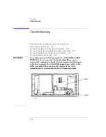
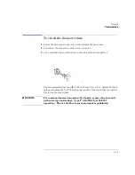
To adjust total power
Description
The total power is adjusted by a potentiometer. The potentiometer is located
on the A5 Laser Driver Board Assembly.
Procedure
1
Remove the instrument’s top and bottom covers.
2
Connect a power meter to the Agilent 83438A’s front-panel
OPTICAL OUT
connector.
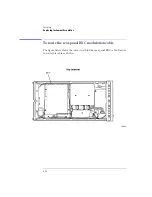
3
Locate R18 on the A5 Laser driver board assembly for the pump laser. See the
following figure.
4
Adjust potentiometer R18 on the A5 Laser driver board assembly to set the
output power b5.5 dBm and +8.1 dBm (3.6 mW to 6.5 mW).
Summary of Contents for 83437A
Page 1: ...Agilent 83438A Erbium ASE Source User s Guide ...
Page 5: ...v The Agilent 83438A At a Glance Rear view of instrument ...
Page 8: ......
Page 10: ......
Page 24: ...2 4 Making Measurements Performing Stimulus Response Measurements ...
Page 41: ...3 Specifications 3 3 Regulatory Information 3 6 Specifications and Regulatory Information ...
Page 48: ......
Page 54: ......
Page 61: ...5 7 Servicing General Information ...
Page 63: ...5 9 Servicing General Information ...
Page 79: ...5 25 Servicing Adjustment Procedure ...
Page 85: ...5 31 Servicing Replacing Instrument Assemblies Location of resistors R2 R8 and R9 ...
Page 92: ...5 38 Servicing Replaceable Parts ...
Page 94: ...5 40 Servicing Replaceable Parts ...
Page 96: ...5 42 Servicing Replaceable Parts ...
Page 98: ...5 44 Servicing Replaceable Parts ...
Page 100: ...5 46 Servicing Replaceable Parts ...
Page 106: ......