


5-4
Servicing
General Information
General Information
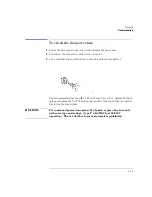
Whenever you contact Agilent Technologies about your Agilent 83438A, have
the complete serial number and option designation available. This will ensure
you obtain accurate service information.
for a list of internal labels.
for a list of service tools.
for the location of each instrument assembly.
for the location of each cable.
Clean the cabinet using a damp cloth only.
Protect against ESD damage
Electrostatic discharge (ESD) can damage or destroy electronic components.
All work on electronic assemblies should be performed at a static-safe work
station. Refer to “Electrostatic Discharge Information” on page 5-10 for more
information on preventing ESD.
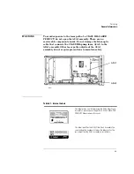
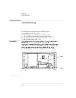
A2 ASE Source Assembly
The A2 ASE Source Assembly can not be repaired. It must be returned to Agi-
lent Technologies for service as a complete unit. The following assemblies are
included in the A2 ASE Source Assembly. Refer to “Major Assemblies” on
page 5-6.
A2A1 Fiber Track Assembly
A2A2 Laser Modulation Board Assembly
A2A3 Pump Laser
A2MP1 Laser heat sink
A2MP2 Optical deck sheet metal
C A U T I O N
Do not remove any of the screws or open the cover on the A2A1 Fiber Track
Assembly. Disturbing the routing of the internal fiber-optic cable could degrade
instrument performance. There are no serviceable components inside this
assembly. Return the complete A2 ASE Source Assembly to Agilent
Technologies for service.
Summary of Contents for 83437A
Page 1: ...Agilent 83438A Erbium ASE Source User s Guide ...
Page 5: ...v The Agilent 83438A At a Glance Rear view of instrument ...
Page 8: ......
Page 10: ......
Page 24: ...2 4 Making Measurements Performing Stimulus Response Measurements ...
Page 41: ...3 Specifications 3 3 Regulatory Information 3 6 Specifications and Regulatory Information ...
Page 48: ......
Page 54: ......
Page 61: ...5 7 Servicing General Information ...
Page 63: ...5 9 Servicing General Information ...
Page 79: ...5 25 Servicing Adjustment Procedure ...
Page 85: ...5 31 Servicing Replacing Instrument Assemblies Location of resistors R2 R8 and R9 ...
Page 92: ...5 38 Servicing Replaceable Parts ...
Page 94: ...5 40 Servicing Replaceable Parts ...
Page 96: ...5 42 Servicing Replaceable Parts ...
Page 98: ...5 44 Servicing Replaceable Parts ...
Page 100: ...5 46 Servicing Replaceable Parts ...
Page 106: ......