


2-8
Making Measurements
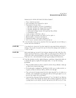
Ambient Light Suppression
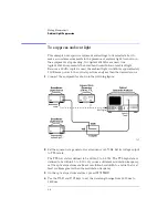
To suppress ambient light
This example uses specific equipment and settings to demonstrate how to
make accurate measurements in the presence of ambient light. As shown in
the equipment setup drawing, two Agilent 83438As are used. One
Agilent 83438A represents the broadband contribution of ambient light.
Because a 12 dB coupler is used, the ambient light contributes approximately
10 dB more power to the optical spectrum analyzer than the desired source.
1
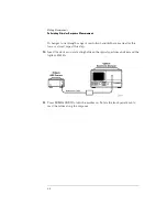
Connect the equipment as shown in the following figure.
2
Set the square-wave generator for a frequency of 270 Hz. Set its voltage output
to TTL levels.
The TTL low state is defined to be within 0 to 0.8 Vdc. The TTL high state is
defined to be within 2.0 to 5 Vdc. If you use a different modulation frequency,
set the optical spectrum analyzer’s resolution bandwidth to a value that is at
least six times greater than the modulation frequency.
3
On the optical spectrum analyzer, press
INSTR PRESET
.
4
Use the
START
and
STOP
keys to set the wavelength range from 1500 nm to
1600 nm.
Summary of Contents for 83437A
Page 1: ...Agilent 83438A Erbium ASE Source User s Guide ...
Page 5: ...v The Agilent 83438A At a Glance Rear view of instrument ...
Page 8: ......
Page 10: ......
Page 24: ...2 4 Making Measurements Performing Stimulus Response Measurements ...
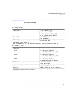
Page 41: ...3 Specifications 3 3 Regulatory Information 3 6 Specifications and Regulatory Information ...
Page 48: ......
Page 54: ......
Page 61: ...5 7 Servicing General Information ...
Page 63: ...5 9 Servicing General Information ...
Page 79: ...5 25 Servicing Adjustment Procedure ...
Page 85: ...5 31 Servicing Replacing Instrument Assemblies Location of resistors R2 R8 and R9 ...
Page 92: ...5 38 Servicing Replaceable Parts ...
Page 94: ...5 40 Servicing Replaceable Parts ...
Page 96: ...5 42 Servicing Replaceable Parts ...
Page 98: ...5 44 Servicing Replaceable Parts ...
Page 100: ...5 46 Servicing Replaceable Parts ...
Page 106: ......