


FINAL
TRIM
SIZE
:
7.5
in
x
9.0
in
Calibration
Overview
performed
regularly
in
order
to
ensure
proper
measurement
accuracy
and
repeatability
.
C
A
U
T
I
O
N
The
input
circuits
can
be
damaged
by
electrostatic
discharge
(ESD).
A
void
applying
static
discharges
to
the
front-panel
input
connectors
.
Before
connecting
a
coaxial
cable
to
the
connectors
,
momentarily
short
the
center
and
outer
connectors
of
the
cable
together
.
A
void
touching
the
front
panel
input
connectors
without
rst
touching
the
frame
of
the
instrument.
Be
sure
that
the
instrument
is
properly
earth-grounded
to
prevent
buildup
of
static
charge
.
It
is
strongly
recommended
that
an
antistatic
mat
and
wristband
be
used
when
connecting
to
electrical
channel
inputs
.
Calibration
interval
Agilent
T
echnologies
recommends
that
the
factory
calibration
be
performed
on
a
periodic
basis
.
Agilent
designs
instruments
to
meet
specications
over
the
recommended
calibration
interval
provided
that
the
instrument
is
operated
within
the
specied
operating
environment.
T
o
maintain
specications
,
periodic
recalibrations
are
necessary
.
W
e
recommend
that
the
plug-in
module
be
calibrated
at
an
Agilent
T
echnologies
service
facility
every
12
months
.
Users
are
encouraged
to
adjust
the
calibration
cycle
based
on
their
particular
operating
environment
or
measurement
accuracy
needs
.
Required
warm-up
time
The
instrument
requires
a
1
hour
warm-up
period
before
any
of
the
calibrations
mentioned
in
this
chapter
are
performed.
It
is
not
enough
for
the
instrument
to
be
in
the
standby
setting.
It
must
be
turned
on
and
running
for
the
entire
hour
.
Remote
operation
Remote
programming
commands
for
calibrations
are
included
in
the
A
gilent
83480A/A
gilent
54750A
Programming's
Guide.
P
erforming
calibrations
remotely
is
slightly
dierent
than
the
operation
of
front-panel
calibrations
.
3-3
Summary of Contents for 54751A
Page 1: ......
Page 8: ...FINAL TRIM SIZE 7 5 in x 9 0 in Declaration of Conformity vii ...
Page 9: ...FINAL TRIM SIZE 7 5 in x 9 0 in viii ...
Page 15: ...FINAL TRIM SIZE 7 5 in x 9 0 in Contents ...
Page 16: ...FINAL TRIM SIZE 7 5 in x 9 0 in 1 The Instrument at a Glance ...
Page 22: ......
Page 25: ...FINAL TRIM SIZE 7 5 in x 9 0 in TheInstrumentata Glance ...
Page 26: ...FINAL TRIM SIZE 7 5 in x 9 0 in 2 Channel Setup Menu ...
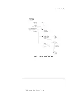
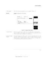
Page 28: ...FINAL TRIM SIZE 7 5 in x 9 0 in ChannelSetupMenu Figure2 1 ElectricalChannel Setupmenu 2 3 ...
Page 38: ...FINAL TRIM SIZE 7 5 in x 9 0 in 3 Calibration Overview ...
Page 52: ...FINAL TRIM SIZE 7 5 in x 9 0 in 4 Speci cations and Characteristics ...
Page 60: ......
Page 67: ...FINAL TRIM SIZE 7 5 in x 9 0 in InCaseofDi culty ...


