


FINAL
TRIM
SIZE
:
7.5
in
x
9.0
in
Channel
Setup
Menu
NNNNNNNNNNNNNNNNNNNNNNNNNNNNNNNNNNN
Attenuation
The
Attenuation
function
lets
you
select
an
attenuation
that
matches
the
device
connected
to
the
instrument.
When
the
attenuation
is
set
correctly
,
the
instrument
maintains
the
current
scale
factors
,
if
possible
.
All
marker
values
and
voltage
or
wattage
measurements
will
reect
the
actual
signal
at
the
input
to
the
external
device
.
The
attenuation
range
is
from
0.0001:1
to
1,000,000:1.
When
you
connect
a
compatible
active
probe
to
the
probe
power
connector
,
adjacent
to
the
corresponding
channel
input,
the
instrument
automatically
sets
the
attenuation.
F
or
all
other
devices
,
set
the
probe
attenuation
with
the
knob
,
arrow
keys
,
or
keypad.
N
O
T
E
Refer
to
Chapter
3
for
information
on
calibrating
to
the
tip
of
the
probe
.
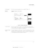
K
ey
Path
4
Channel
5
NNNNNNNNNNNNNNNNNNNNNNNNNNNNNNNNNNNNNNNNNNNNNNNNNNNNNNNNNNNNNN
External
scale
.
.
.
NNNNNNNNNNNNNNNNNNNNNNNNNNNNNNNNNNN
Attenuation
2-8
Summary of Contents for 54751A
Page 1: ......
Page 8: ...FINAL TRIM SIZE 7 5 in x 9 0 in Declaration of Conformity vii ...
Page 9: ...FINAL TRIM SIZE 7 5 in x 9 0 in viii ...
Page 15: ...FINAL TRIM SIZE 7 5 in x 9 0 in Contents ...
Page 16: ...FINAL TRIM SIZE 7 5 in x 9 0 in 1 The Instrument at a Glance ...
Page 22: ......
Page 25: ...FINAL TRIM SIZE 7 5 in x 9 0 in TheInstrumentata Glance ...
Page 26: ...FINAL TRIM SIZE 7 5 in x 9 0 in 2 Channel Setup Menu ...
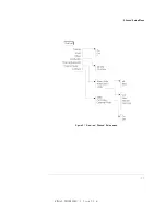
Page 28: ...FINAL TRIM SIZE 7 5 in x 9 0 in ChannelSetupMenu Figure2 1 ElectricalChannel Setupmenu 2 3 ...
Page 38: ...FINAL TRIM SIZE 7 5 in x 9 0 in 3 Calibration Overview ...
Page 52: ...FINAL TRIM SIZE 7 5 in x 9 0 in 4 Speci cations and Characteristics ...
Page 60: ......
Page 67: ...FINAL TRIM SIZE 7 5 in x 9 0 in InCaseofDi culty ...


