background image

14

C h a p t e r   1   — 


P r e p a r i n g   t h e   s c a n n e r 

1 .  

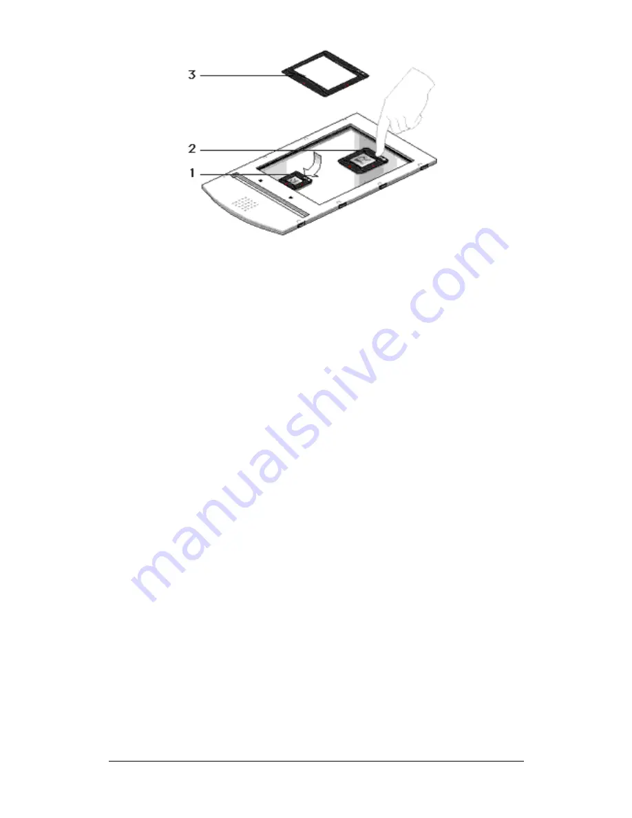
3 5  m m  r e g u l a r  s l i d e  h o l d e r 

2 .  

6  x  6  c m  r e g u l a r  s l i d e  h o l d e r 

3 .  

4  x  5  i n c h  r e g u l a r  s l i d e  h o l d e r 

T h e  s p e c i f i c a t i o n s  ( r e s o l u t i o n , . . . )  o f  t h e  s c a n n e r  a p p l y  t o  t h e  w h o l e  s c a n  a r e a . 
H o w e v e r ,  i m a g e  q u a l i t y  i s  a l w a y s  a t  i t s  o p t i m u m  i n  t h e  m i d d l e  o f  t h e  s c a n  a r e a . 

Summary of Contents for DuoScan HiD

Page 1: ...r This chapter shows you how to set up your DuoScan HiD for the Apple Macintosh and PC Appendix A Troubleshooting This appendix can be helpful when you come across problems that you are unable to solve Appendix B Technical information This appendix provides specifications of your DuoScan HiD Appendix C DuoScan HiD regulation compliance This appendix gives you information on the safety regulations ...

Page 2: ...emark of Intel Corporation Power Macintosh and System 8 are trademarks and Apple and Macintosh are registered trademarks of Apple Computer Incorporated Windows Windows NT and the Windows logo are trademarks or registered trademarks of Microsoft Corporation Other products or company names are trademarks or registered trademarks of their respective holders Copyright 1999 Agfa Gevaert N V All rights ...

Page 3: ...batch slide holder 16 6 x 9 cm batch slide holder 4 x 5 inch batch slide holder 17 Performing a power on test 19 Chapter 2 Installing the scanner 20 Minimum hardware requirements and recommendations 21 Environmental requirements 22 Precautions 22 Cleaning your scanner 23 SCSI devices 23 Installation for the Apple Macintosh 24 Which SCSI interface card 24 Choosing a SCSI ID number 24 Connecting the...

Page 4: ...ation Compliance 42 Safety regulations 42 UL Safety Statement 42 FTZ Bescheinigung des Herstellers Importeurs 42 TÜV Wichtige Sicherheitshinweise 42 Electromagnetic interference 43 Federal Communications Commission Radio Frequency Interference Statement 43 Canadian department of Communications 44 ...

Page 5: ...pness and color fidelity The universal glass frame the slide holder frame and the batch slide holders allow you to scan transparent originals without using the reflective glass plate Three regular slide holders are supplied with DuoScan HiD together with several types of batch slide holders which are available as an option in order to increase the productivity of the scanner The document cover is ...

Page 6: ...ns for Unpacking the scanner Unlocking the scanner Relocking the scanner Taking a closer look Placing reflective originals Placing transparent originals Using the universal glass frame Using the regular slide holders Using batch slide holders 35 mm framed batch slide holder 35 mm strip batch slide holder 6x9cm or 4x5inch batch slide holder Performing a power on test ...

Page 7: ...the Warranty and Registration card Only then can you claim your guarantee and get information on new products and upgrades Unlocking the scanner The scanner s optical carriage contains all optical components and rides back and forth during the scan An unlocking screw holds it in place at the right side of the scanner during shipment You must remove this screw before powering up the scanner 1 Pull ...

Page 8: ...canner s optical assembly from possible damage 1 Switch your scanner on 2 Pull the scanner forwards on the edge of the table until you can see the unlocking screw on the bottom of the scanner 3 Take a coin and turn the screw a quarter clockwise The screw is fastened your scanner is locked 4 Move the scanner back on your desktop 5 Turn your scanner off ...

Page 9: ...look so that you become familiar with its parts This figure illustrates the locations of the different parts of your DuoScan HiD 1 2 3 5 6 7 8 4 1 adjustable document cover 2 reflective glass plate 3 rulers 4 transparency tray 5 power switch 6 power indicator 7 transparency ready indicator 8 reflective ready indicator ...

Page 10: ...10 Chapt er 1 Preparing t he s c anner 1 power input 2 SCSI terminator switch 3 SCSI ID switch 4 25 pin connector 5 50 pin connector ...

Page 11: ... er 1 Preparing t he s c anner 11 1 Universal glass frame 2 Slide holder frame 3 6 x 9 cm batch slide holder 4 35 mm framed batch slide holder 5 35 mm strip batch slide holder 6 4 x 5 inch batch slide holder ...

Page 12: ...he scan area However for the most common resolutions used for reflective originals placing originals to the side will not decrease quality 3 Close the document cover of the scanner Placing transparent originals When you scan transparent originals you use either a batch slide holder frame or the universal glass frame 1 2 3 1 universal glass frame 2 calibration slit 3 arrow indicating where to place...

Page 13: ...ing in front of the scanner and that it is clean Using the regular slide holders You can also put your originals in a regular slide holder to avoid blooming and newton rings There are three types of regular slide holders 35 mm strip 6 x 6 cm and 4 x 5 inch To scan a transparent original using a regular slide holder carry out the following instructions 1 Put your original in a slide holder 2 Center...

Page 14: ...5 mm regular slide holder 2 6 x 6 cm regular slide holder 3 4 x 5 inch regular slide holder The specifications resolution of the scanner apply to the whole scan area However image quality is always at its optimum in the middle of the scan area ...

Page 15: ... slide into the frame 1 Locate the edge of the slide into the indentation on the arm of the holder 2 Push the slide down into the aperture 3 Ensure that the slide is secured by the six fixing lugs on the inside of the frame The slide position might need slight adjustment after location 4 When all the slides have been mounted locate the batch slide holder into the batch slide holder frame Remove a ...

Page 16: ...ip slide frame by placing your thumb on the raised points on the end of the holder and pushing the strip slide frame towards the hinge slot The frame will become loose 2 Lift the strip slide frame 3 Place the strip of slides into the centre of the frame 4 Close the frame 5 Lock the frame in position by sliding away from the hinge slot The position of the slides can be readjusted slightly by moving...

Page 17: ...nto the batch slide holder frame To mount or remove slides for the 6 x 9 cm and the 4 x 5 inch slide holders you have to apply the same principles Mount a slide into the frame 1 Unlock the frame by placing your thumb on the raised points on the end of the holder and pushing the frame towards the hinge slot The frame will become loose 2 Lift the frame 3 Locate the slide against the front edge of th...

Page 18: ...emove a slide from the frame 1 Unlock the frame by placing your thumb on the raised points on the end of the holder and pushing the frame towards the hinge slot The frame will become loose 2 Lift the frame 3 Remove the slide 4 Close the frame ...

Page 19: ...rresponds with the voltage in your area If not call your dealer or Agfa service representative 3 Switch on the scanner The scanner performs a self test during which the power indicator light green switches on and the reflective ready indicator light yellow and the transparency ready indicator light yellow remain blinking This takes about half a minute After the self test the power indicator and th...

Page 20: ... about Minimum Hardware requirements and recommendations Environmental requirements Precautions Cleaning your scanner SCSI devices Installation for the Apple Macintosh Which SCSI interface card Choosing a SCSI ID number Connecting the scanner Testing the connection Installation for the PC Which SCSI interface card Choosing a SCSI ID number Connecting the scanner Testing the connection ...

Page 21: ...nning Windows 95 Windows 98 or NT 4 0 for Intel platforms o An ASPI compatible SCSI card In general FotoLook supports all fully WINASPI compatible cards Some SCSI cards require a special SCSI cable e g wide SCSI Contact your supplier for the proper cable v Note Please read the installation and set up guidelines in the documentation that is supplied together with your SCSI interface card In case of...

Page 22: ...your own safety and that of your equipment respect conscientiously the environmental requirements see the above section and always take the following precautions C au t io n For the reason of safety besides the personal maintenance mentioned in this owner s guide don t try to remove any mechanical parts or any electronic devices If your scanner needs servicing our dealer and service offices are av...

Page 23: ... the liquid to penetrate and contaminate the mirrors and lenses inside the scanner Do not use detergent on the plastic parts of your scanner n The cleaning of the calibration slit in the transparency holder frame is especially important Keep this area dust and dirt free SCSI devices DuoScan HiD is a Small Computer System Interface SCSI device It communicates with your computer by using the SCSI 2 ...

Page 24: ...mmended to use together with your DuoScan HID v Note Please check the following documentation o The documentation supplied with your interface card This will tell you how to install the card o If you are using third party software check the documentation supplied with that software for the SCSI interface cards supported Choosing a SCSI ID number Before you connect your DuoScan HiD to your Macintos...

Page 25: ...our DuoScan HiD is preset to ID 2 4 If SCSI ID number 2 is free go to instruction 5 If SCSI ID number 2 is already assigned you need to set the scanner to a free SCSI ID number o Make sure your scanner is switched off and is disconnected from your computer o Decide on an unassigned SCSI ID number o Use the SCSI ID switch see figure at the rear of the scanner to set the desired SCSI ID o Push above...

Page 26: ...on For safety reasons never use extension cables for power cables Always make sure there are no more than two terminators in your SCSI chain one at the beginning and one at the end Some SCSI devices have built in terminators and must therefore be placed at the beginning or end of your SCSI chain Please check the documentation of each of your SCSI devices if you re not sure whether the device has a...

Page 27: ... 2 I ns t alling t he s c anner 27 If your DuoScan HiD is the only SCSI device to be connected to your Apple Macintosh 1 Connect the smaller 25 pin end of the SCSI cable to the connector of your Apple Macintosh ...

Page 28: ...cted to your Apple Macintosh together with other SCSI devices If you install the scanner at the end of your SCSI chain 1 Remove the terminator from the last device in the SCSI chain 2 Connect the 50 pin end of the SCSI cable to the connector that has become available on this device 3 Connect the 25 pin end of the SCSI cable to the free connector of the scanner 4 Snap the diamond shaped wire clips ...

Page 29: ...SCSI cable from one of these two SCSI devices 2 Connect the free end of this SCSI cable to the scanner 3 Connect the 50 pin end of the SCSI cable the one supplied with your scanner to the other adjacent SCSI device 4 Connect the 25 pin end of the SCSI cable the one supplied with your scanner to the scanner 5 Snap the diamond shaped wire clips into the clip brackets to secure the connection ...

Page 30: ...he scanner on The scanner performs a self test the power indicator light switches on and the two other indicator lights start blinking After the self test all the scanner s indicator lights switch on 4 Switch on any other SCSI devices you may have attached and wait for them to start up 5 Switch on your Macintosh As it starts up your Macintosh performs a series of tests to verify the correct system...

Page 31: ...n HID v Note Please check the following documentation o The Read Me file on the PC scanner driver software disk for up to date information o The documentation supplied with your interface card This will tell you how to install the card o If you are using third party software check the documentation supplied with that software for the SCSI interface cards supported Choosing a SCSI ID number Before ...

Page 32: ...er to a free SCSI ID number o Make sure your scanner is switched off and is disconnected from your computer o Decide on an unassigned SCSI ID number o Use the SCSI ID switch at the rear of the scanner to set the desired SCSI ID o Push above the SCSI ID number to decrease the number push underneath the SCSI ID number to increase the number 4 Close the utility ...

Page 33: ...ng and one at the end Some SCSI devices have built in terminators and must therefore be placed at the beginning or end of your SCSI chain Please check the documentation of each of your SCSI devices if you re not sure whether the device has a built in terminator Because your HiD DuoScan has a built in terminator you do not need to use an external terminator To activate the built in terminator switc...

Page 34: ...rger 50 pin end of the SCSI cable to the connector at the rear of your PC Use the SCSI cable supplied with the scanner 3 Connect the smaller 25 pin end of the SCSI cable to the free connector of the scanner If your PC has a 50 pin connector and your DuoScan HiD will be connected to your PC together with other SCSI devices 4 Snap the diamond shaped wire clips into the clip brackets to secure the co...

Page 35: ... information see Choosing a SCSI ID number earlier in this chapter 2 Connect the 50 pin end of the SCSI cable to the connector at the rear of your device Use the cable supplied with the scanner 3 Switch the internal terminator on 4 Snap the diamond shaped wire clips into the clip brackets to secure the connection 5 Connect the 25 pin end of the SCSI cable to the scanner ...

Page 36: ... scanner to an unused SCSI ID number between 1 and 6 For more information see Choosing a SCSI ID number earlier in this chapter 3 Connect the 50 pin end of the SCSI cable to the connector at the rear of the adjacent device Use the cable supplied with the scanner 4 Connect the 25 pin end of the cable to the scanner s 25 pin connector 5 Connect the scanner to the next device in the SCSI chain 6 Make...

Page 37: ...light green switches on and the ready indicator lights yellow start blinking After the self test the scanner s power indicator light switches on 4 Switch on any other SCSI devices you may have attached and wait for them to start up 5 Switch on your PC 6 Check if the scanner is present For Windows 95 98 1 Right click My Computer 2 Select properties 3 Select the Device Manager tab Agfa Scanners for ...

Page 38: ...lock properly or call your service representative The ready indicator light yellow on the scanner s operating panel remains blinking or goes off after the power up sequence about half a minute n A malfunction has been detected by the scanner n Check if you have unlocked the scanner If this can not be the problem please contact your dealer or Agfa service representative The power indicator fails to...

Page 39: ...cker n Maybe you did not wait long enough for all SCSI devices to start up before you switched your workstation on Therefore try restarting your workstation If this doesn t help n Disconnect all SCSI devices and connect them one by one beginning with the scanner to identify the device that causes the problem The scanner reports errors during scanning Apple Macintosh n Check the status of the SCSI ...

Page 40: ...ppi A D Conversion 42 bit 14 bit color Output pixel depth 1 bit output for line art black and white 8 or 14 bit output for gray 24 or 48 bit output for color Density range 3 2 D Max density detected 3 7 D Scanning speed 7 20 ms line Original sizes A4 or Legal Maximum scan area Maximum reflection 8 x 14 inch 203 x 355 mm Maximum transmission 8 x 10 inch 203 x 254 mm transparency Memory 1 Mb RAM Ref...

Page 41: ...consumption 40 W Dimensions 400 mm 16 inch x 182 mm 7 inch x 613 mm 24 inch W x H x L Weight 13 5 kg Acoustic noise max 55 dB in worst condition Interface SCSI 2 interface Maximum throughput 4 MB sec Environment Operating temperature 10 C to 35 C 50 F to 95 F Relative humidity 10 to 85 ...

Page 42: ... wird bescheinigt dass der Image Scanner in Übereinstimmung mit den Bestimmungen der vgf 1046 1984 funk entstört ist Der Deutschen Bundespost wurde das inverkehrbringen dieses Gerätes angezeigt und Berechtigung zur Überprüfung der Serie auf Einhaltung der Bestimmungen eingeraumt TÜV Wichtige Sicherheitshinweise 1 Bitte Lesen Sie sich diese Hinweise sorgfältig durch 2 Um eine Beschädigung des Gerät...

Page 43: ...rence when the equipment is operated in a residential installation This equipment generates uses and can radiate radio frequency energy and if not installed and used in accordance with the instruction manual may cause harmful interference to radio communications However there is no guarantee that interference will not occur in a particular installation If this equipment does cause harmful interfer...

Page 44: ...digital apparatus set out in the Radio Interference Regulations of the Canadian Department of Communications Le présent appareil numérique n émet pas de bruits radioélectriques dépassant les limites applicables aux appareils numériques de la classe B prescrites dans le Règlement sur le brouillage radioélectrique édicté par le ministère des Communications du Canada ...

Reviews: