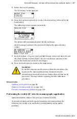
3.
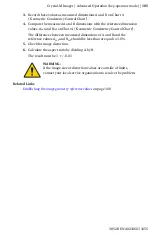
Record these values as measured dimensions A and B on Chart 4
(‘Geometric Consistency Control Chart’).
4.
Compare the measured A and B dimensions with the reference dimension
values, A
ref
and B
ref
on Chart 4 (‘Geometric Consistency Control Chart’).
The differences between measured dimensions of A and B and the
reference values A
ref
and B
ref
should be less than or equal to 1.0%.
5.
Check for image distortion.
6.
Calculate the aspect ratio by dividing A by B.
The result must be 1 +/- 0.01
WARNING:
If the image size or distortion values are outside of limits,
contact your local service organization to resolve the problem.
Related Links
Establishing the image geometry reference values
on page 100
Crystal-M Imager | Advanced Operation (key-operator mode) |
105
3852B EN 20210601 1655
Summary of Contents for 5367/300
Page 1: ...Crystal M Imager 5367 300 User Manual 3852B EN 20210601 1655 ...
Page 12: ...12 Crystal M Imager Crystal M Imager 3852B EN 20210601 1655 ...
Page 57: ... The display Crystal M Imager Introduction 57 3852B EN 20210601 1655 ...
Page 161: ...Crystal M Imager Plug Play Installation Manual 161 3852B EN 20210601 1655 ...


