background image

:

ANAPURNA XL²


OPERATOR MANUAL


A

B]]]]]]]]]]]]]]]]]]]]]]]]]]]]]]]]]]]]]]]]]]]]]]]]]]]]]]]]]]]]]]]]]]]]]]]]]]]]]]]]]]]]]]]]]]]]]]]]]]]]]]]]]]]]]]]]]]]]]]]]]]]]]]]]]]]]]]]]]]]]]]]]]]]]]]]]]]]]]]]]]]]]]]]]]]]]]]]]]]]]]]]]]]]]]]]]]]]]]]]]]]]]]]]]]]]]]]]]]]]]]]]]]]]]

21

]

8/08/2008

]

8

8

8

8. 

. Maintenance

Maintenance

Maintenance

Maintenance....    


8.1. General information 


-


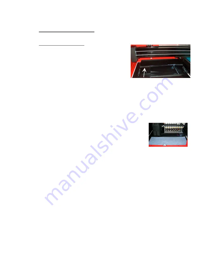
At the end of the day, and when you stop 
printing, the shuttle needs to be placed in the  
“Purge position”. For overnight or longer 
standstill times, an absorbing cloth or paper has 
to be placed onto the “Grid” underneath the 
shuttle and this grid must be pulled to the front. 
This will take care to catch the ink drops that are 
jetted continuously to weep the heads, and 
avoids that the ink drops will contaminate the 
whole area around the shuttle.  

 
-


Dispose that paper in the morning, when you want to start printing again with the 
printer. 

 
- A default “Weeping” time is set in the engine  
  software to keep the heads open, this small amount of ink is collected in     
  the underneath waste box, which leads to a waste tank underneath the engine. 
  (See chapter 5.6, on how to empty) 
 
- Place some towels in front of the Purge grid, this will help to  
  keep the area clean, it’s advisable to replace them weekly.  
 
 
- During a print job, the “Purge Grid” must be placed forward when you start to print. 

This prevents the UV light reflection onto the ink heads  and so prevents to cure the 
ink into the head nozzles when the UV-lamps pass over the much lower purge tray. 
It also prevents the ink in the underneath waste box from getting cured by the UV  
lamps during the printing stage.  


Summary of Contents for 1

Page 1: ... ANAPURNA ANAPURNA ANAPURNA ANAPURNA XL XL XL XL OPERATOR MANUAL version 1 0 AB ...

Page 2: ...Maintenance 18 7 4 Replacement 20 8 Maintenance 21 8 1 General information 21 8 2 Daily Maintenance Nozzle check purge 22 8 3 Weekly Maintenance 25 8 4 Long Stand Still 26 8 5 Bleeding air out of the ink filters 28 9 Media Setup 29 9 1 Roll to Roll 29 9 1 1 Auto Feed System 29 9 1 2 Take Up control system 30 9 1 3 Roll Alignment 30 9 1 4 Vacuum 30 9 2 Rigid Media 31 9 2 1 Rigid Support tables 31 9...

Page 3: ...ly to the UV light If you need to look at the direction of the light wear protective glasses or look through the front cover glas WARNING UV ink contains chemicals when handling the ink wear protective gloves to protect your skin and protective glasses Should the ink come in contact with your skin wash with water immediately IMPORTANT The Anapurna engines are equipped with an exhaust system to ext...

Page 4: ...nd Features 2 Printer Overview and Features 2 Printer Overview and Features 2 Printer Overview and Features System Dimensions System Dimensions System Dimensions System Dimensions ANAPURNA XL Max media width 2 5m printable width 2 48m 2 1 Front view parts locations ...

Page 5: ... ANAPURNA XL OPERATOR MANUAL AB 5 8 08 2008 2 2 Rear view parts locations ...

Page 6: ...y sensor on the Front and Rear cover Carrige movement and printing can only be done with covers closed 1 When carriage is waiting Purge or Home When a cover is open you will see the door open error on the screen and the carriage will not move to Home or Purge if requested 2 During printing When you open the cover at this stage the PRINT will be CANCELLED and the UV lamp shutter will be closed auto...

Page 7: ... ANAPURNA XL OPERATOR MANUAL AB 7 8 08 2008 2 3 Head Carriage view parts 2 4 Signal tower ...

Page 8: ...dpi White heads White heads White heads White heads Spectra Spectra Spectra Spectra Galaxy 256 8 Galaxy 256 8 Galaxy 256 8 Galaxy 256 80 AAA JA Jetting Assembly 0 AAA JA Jetting Assembly 0 AAA JA Jetting Assembly 0 AAA JA Jetting Assembly Calibrated Drop Size 75 pl 256 addressable jetting nozzles single line Nozzle spacing 256 microns 0 010 Intrinsic resolution 100 dpi 8 JA mounted in head base pl...

Page 9: ...using Light Cyan and Light Magenta Results in smooth highlights Ink usage 10ml m all colors together 6 4 2 Color gamut Agfa Inks tuned towards the ISO Standard 12647 2004 Calculated nr of colors Volume calculated within Monaco CMS ISO Standard 12647 770 000 colors Anapurna Ink on Anapurna printing in 6 pass 6 pass 6 pass 6 pass 830 000 colors 8 pass 8 pass 8 pass 8 pass 850 000 colors 12 pass 12 p...

Page 10: ...he Signal tower Ink can be refilled in while printing White ink tank has a continuous working stirring rod inside Tanks WARNING ONLY refill with the 1liter bottle when the low level alarm goes off At that point you can pour in a complete 1L bottle and you won t have any left over ink remaining in the bottle 5 2 Auto ink supply From the ink tank ink is pumped into the Sub ink tank which is position...

Page 11: ... this stage you also need to Press the AT button to close the procedure button to close the procedure button to close the procedure button to close the procedure 5 3 Sub Ink Tank and head base temperatures Temperature setting Sub Ink Tank Color 40 C White Ink 40 C when in use up to max 45 C 25 C when not in use Temperature setting Headbase plate 40 C Read out How to make changes ...

Page 12: ...BE FOUND IN THE MAINTENANCE CHAPTER 5 4 The 2 Way valves Normal printing The color valves are positioned in the I direction The ink can flow to the head Purging the heads In case of clogged nozzles or misfiring nozzles Push the Purge button at very short intervals this will cause ink flowing through the heads this will un clog the missing nozzles make sure the Grid is pushed to the back Cleaning t...

Page 13: ...t that moment When you have to raise the under pressure to a higher then normal value to avoid ink dripping out of the heads pooling then this can be an indication that some air got into the ink supply lines In this case refer to the maintenance section to do a large purge and get rid of air in the nozzles by leaking the heads with low under pressure If this is not sufficient air can be present in...

Page 14: ...the blue lamp will flash on the Signal tower together with a beep alarm The waste tank is located under the conveyor belt on the Purge side of the engine Open the tap underneath to empty the tank Make sure the UV ink is kept separately from solvent ink do not mix them in a waste container ...

Page 15: ... power 120 W cm 2 fixed settings Full and half strength Air cooled lamp house Quick and easy replacement of the UV bulbs Always change both the lamps Use of an automated shutter system 6 2 Curing setup and sequences Settings in software Lamps continous ON lamp stays ON for next print longest lifetime WarmUp Time when turning back on the UV lamps before ready state Cooling Time after turning off th...

Page 16: ...n the heat resistance thickness of your media you can set the UV lamp power to Half or Full power By default Full power should be used whenever possible By default Full power should be used whenever possible By default Full power should be used whenever possible By default Full power should be used whenever possible Note about UV lamp life time The lamp life time is not only depending on the numbe...

Page 17: ...The border of each compartment is indicated with a yellow sticker on the box beam It is very important to set the air valves depending on the media width and media type that you are using As a general rule one has to close the corresponding air valve to the 30 degrees angle position so close the valve for 2 3 of its range if the corresponding table compartment is completely covered by the media Th...

Page 18: ...nger length in between the belt and the vacuum table at front side If he can put the hand further under the belt the belt needs re tension remove the metal covers on the backside both left and right rotate the screw at the REAR stand to CW clock wise to put the tension higher Do this correction with the same numbers of turns left and right Unequal tension if the tension left and right is different...

Page 19: ...hat the belt is masked so printing on the belt is reduced to a minimum When you have printed onto the Conveyor belt and the ink is cured it can not be removed anymore and ink can be build up under the conveyor belt and result in a loss of vacuum re align the belt tensioning the belt see previous paragraph ...

Page 20: ...NA XL OPERATOR MANUAL AB 20 8 08 2008 7 4 Replacement of Conveyor belt Vacuum can become insufficient when the belt is completely printed The Conveyor belt therefore is a Spare Part and can be ordered as such ...

Page 21: ...aper in the morning when you want to start printing again with the printer A default Weeping time is set in the engine software to keep the heads open this small amount of ink is collected in the underneath waste box which leads to a waste tank underneath the engine See chapter 5 6 on how to empty Place some towels in front of the Purge grid this will help to keep the area clean it s advisable to ...

Page 22: ...by the number that is displayed in the textbox in the test menu The default number 500 refers to the position indicated by the white dots on the beam box The red area shows the placement of the Spot and Pré white if it s turned on use a black or colored paper to see the white Switch on the vacuum select Test to start the print Evaluate the nozzle check for missing nozzles The Jet Test must be carr...

Page 23: ...Purge button frequently at very short intervals Open all heads again switch them back to the I position Clean the heads with a fiber free cloth Check on weeping L L L Large arge arge arge purge purge purge purge With all the heads open switch them all to the I position Push and hold the Purge button for a longer time 2 sec end the procedure by pushing the Purge button again but now frequent at ver...

Page 24: ...ailing heads to the S position Set the Solution valve to S Push the Solution Purge button on the back of the carriage Keep pushing in a sequence of 2 seconds push and 4 seconds release until you see a CLEAR Solution Curtain under the heads then stop pushing Leave the heads leaking in this condition for at least 5 minutes Set all the valves back to I Give a little purge Set the Neg Pressure to 0 le...

Page 25: ... and close them and in the second stage flush the remaining 4 left heads K C M Y Finally open the 4 right heads again and flush all 8 heads together now By doing so you ll have the most optimal cleaning pressure Switch all heads and the Solution valve back to I Set the Neg Vacuum Pressure to 0 leave the system for 1 minute Ink will now start dripping out the heads Empty the sub airtank by opening ...

Page 26: ...ads together now By doing so you ll have the most optimal cleaning pressure Leave all ink valves in the S position set the Solution valve to I On the Engine s Control Panel perform a Head Lift Up The carriage will go to the highest position Clean the Head Base Plate with a cloth Set the Vacuum Pressure to 0 Negative Pressure Mount the Capping Plate underneath the Head Base Plate use a plastic foil...

Page 27: ... Turn the compressed air back on still at 0 on display Turn ON the main power switch at the rear side of the engine Turn and pull the emergency stop back outwards Startup the engine and switch the engine s PC back on ATTN carriage will move slowly to the Home position Move the carriage back to the Purge position Switch all ink valves back to I Perform a long purge until you see ink appearing out o...

Page 28: ...t pooling there is a big chance that an air bubble is sitting into the ink tank This can be caused by a previous low ink level in the main ink tank by having poured ink into the main tank that contained a lot of air or just an accumulation over time of small air bubbles in the ink At that time the user has to bleed the air out of the ink filters Only then an accurate ink supply can occur ...

Page 29: ...ia with a constant tension and height controlling These are acquired from the signal sensors The Front roll bar will wind the printed media holding a constant tension to reduce distortion Wind direction can be reversed Make sure you always insert the Tension Roll Bar at a correct way The ball bearing must be inside the guide When inserting make sure both side s are positioned as high as possible i...

Page 30: ...e vacuum table and edge of the edge of the vacuum table and edge of the media is identical the same front and rear A difference of 1mm is already too much media is identical the same front and rear A difference of 1mm is already too much media is identical the same front and rear A difference of 1mm is already too much media is identical the same front and rear A difference of 1mm is already too m...

Page 31: ... Alignment 9 2 2 1 Media Register Pins and side guiders When turning the upper Media Set button to position 1 the left side pin indicated as 1 in the below picture goes down This is the side alignment pin of your first rigid rigid A This rigid can be small or even have full engine width When you turn the upper Media Set button to position 2 also side alignment pin nr 2 in the below picture will co...

Page 32: ...d Left Margin Setup The A and B positions the origin point at the corner of your media are known distances The A point has as approximately position Top margin 300 mm and Left Margin 50 mm Depending on the position onto the media where the image has to be printed you have to add the image offset to these numbers These numbers can be entered in the Control program Image placement for printing on tw...

Page 33: ...ing unchanged 9 2 3 Vacuum With rigid media the vacuum settings must be chosen according the covered area on the conveyor belt When printing on two rigid media activate both the vacuum tables 1 2 more info see chapter 7 1 9 3 Media Tension Bars The engine has got one roller bar at the front and one at the back They are located underneath the front and back covers These bars will help to keep the m...

Page 34: ...e following Parameters to set the Head Base Height Gap Enter the value that you want the Head Base to be above the media surface Recommended value 1 5mm For heat sensitive media you can go higher to avoid that too much heat is accepted by the media and as a result the media is extended and can touch the head or is printed with bad quality Change of this value requires however other values as offse...

Page 35: ... are Ok load the media onto the table click on the Set Gap Procedure When you ve entered a 1 5mm Gap Check Distance 1200mm The Head Base will stay in the Home position and go up to the highest limit position 50mm After this movement you have to confirm on screen that the carriage is clear to move to the Check Distance position Shuttle will move to the left until the measure spoon is around 800mm f...

Page 36: ...p forward and Left Margin 9 Setup Menu to Change Parameters 10 Press to Open the TEST menu 11 Select PASS mode 12 Push to start Printing 13 Open image file rtl to be printed 14 Lift head to highest position 50mm 15 Select to Uni Directional printing 16 Single Media Feed steps When you open an image file rtl which is sent from the Rip station you ll get an on screen preview and it will also show th...

Page 37: ...r this he has to press onto the same button which then has the text Return to feed the media back to the position were it was laying down before after finishing the previous print 11 2 Setup Parameter Menu A dat file contains all engine parameters such as the UV settings Carriage speed Bi Dir alignment Step size etc Multiple dat files can be made but it is wise to limit the amount to an absolute m...

Page 38: ...ers are protected because they are only intented to be set by the technician during installation After changing a value use the Save as or Save button and create a new dat file or overwrite the old Changes on Parameters marked with an like speed and weep mode require a Parameter Download in the TEST menu before they become active ...

Page 39: ...want however that a drop that is placed in the computer image file near each other also comes on paper near each other when these drops are printed within a different moving direction different pass A straight line has to stay straight For that a correction in start to jet time is needed to make sure that drops are jetted in front of the real landing place so that the drop lands on the correct pla...

Page 40: ... black ink reference Fine tuning for other colors The first parameter field is general value that counts for all colors This value has to be fine tuned so that a black ink drop will fall onto the same place irrespective if it is fired when the shuttle was moving to the left or to the right Due to small differences in the behaviour of different color inks a fine tune can be done for the other color...

Page 41: ...mage 15cmx15cm with text and a smooth background Evaluate the text sharpness and image smoothness As an indication you can stop the print when it s over half way By doing this you ll have a print with unfinished passes at the end helping you to evaluate the alignment The Bi Dir can be out of focus left or right Look at the end of the interrupted print A Too much left B GOOD C Too much right Change...

Page 42: ...p Size A Dark lines in the print as a result of overlapping passes Increase the Step Size value from e g 11770 to 11800 B White lines in the print as a result of a gap between the passes Decrease the Step Size value from e g 11770 to 11755 After the changing use Save to store the new value in the dat file The new value will become immediately active as soon as it is saved ...

Page 43: ...nting white at the higher speed of 1135 instead of 725 will result in a too high spray of white ink and nozzle drop out A Uni directional print is faster than twice the time of the same image printed bidirectional This because the return speed movement from purge to home occurs not onto the selected speed 725 or 1135 or 1625 but on a higher fixed speed of 1700 As a result you don t loose half your...

Page 44: ...s option allows the user to disable the weeping of color ink when the shuttle is set in purge position Agfa s advise is to leave the option permanently ON Agfa s advise is to leave the option permanently ON Agfa s advise is to leave the option permanently ON Agfa s advise is to leave the option permanently ON The used Spectra Galaxy heads require weeping of ink to keep the nozzles open during a st...

Page 45: ...ustomer has to purge a few times a day a little ion Nevertheless the customer has to purge a few times a day a little ion Nevertheless the customer has to purge a few times a day a little cleaning thru the heads to renew the cleaning into the heads cleaning will go out cleaning thru the heads to renew the cleaning into the heads cleaning will go out cleaning thru the heads to renew the cleaning in...

Page 46: ...UAL AB 46 8 08 2008 11 3 Test Menu 11 3 1 Jet Test See chapter 8 2 Daily Maintenance Nozzle check purge 11 3 2 Nozzle Test This allows you to test 1 nozzle of a particular head The requested nozzle is printed in a straight line ...

Page 47: ... you ve changed a parameter in the Setup file which was marked with an use this feature to validate those new values 11 3 5 Carriage Release Test This feature is mainly intended for a Service engineer it allows the release of the Carriage motor which is normally anchored on both side s After executing it s possible to move the Carriage by hand from right to left IMPORTANT To end this test select R...

Page 48: ...rtionally scaled printout 12 2 Preparing the Anapurna 1 The carriage must be moved to the home position first Always make sure there is NO media or obstructions on the conveyor belt when you move the carriage to the home position 2 Place load the media rigid flexible onto the front side of the belt turn on the vacuum white lamp on tower vacuum is on 3 Check that you are using the correct setup fil...

Page 49: ...and set the Print Mode to the correct passes check Status Message e g 8 pass Ready 3 Set the Top and Left Margin according your desired placement See chapter 9 1 3 and 9 2 2 2 4 Choose between Uni or Bi directional printing 5 Switch on the UV lamps See chapter 6 6 As soon as the green lamp comes up on the tower you can press the PRINT button green lamp on tower UV lamps are ready ...

Page 50: ...t While printing press S and Y the print is then cancelled 12 5 Purge function on the printing While printing press S and N at Purge Request select Y the carriage will move to the Purge position After the Purge intervention press the OK button to continue printing ...

Page 51: ...ia edge on point of return use a white trailer in Wasatch at the right side of your image for rigid media put a rigid of the same height in front and behind the media That way you avoid that open air holes at the start and the end of the plate will make the vacuum lower and allow the media to move during expansion by heat If this is not sufficient or not wanted following actions can be done Rip an...

Page 52: ...4 Positioning of media and use of the vacuum valves The vacuum table is divided in 4 inner compartments The table width is 254 cm so each compartment is about 63 5 cm The borders of these compartments are marked with a yellow bullet onto the beam bar and the compartments are numbered from home to purge in sequence V1 until V4 When positioning the media it is important to lay down the media symmetr...

Page 53: ...over 2 compartments completely since 152 63 5 63 5 Valve Position V4 90 V3 20 V2 20 V1 90 Media width 90 cm covers only 1 compartment completely Valve Position V4 0 V3 90 V2 20 V1 90 V4 V3 V2 V1 Table Rear roller Front roller MEDIA V4 V3 V2 V1 Table Rear roller Front roller MEDIA ...

Page 54: ...V1 90 Media width 230 cm covers 2 compartment completely Valve Position V4 90 V3 20 V2 20 V1 90 Media width 250 cm covers 4 compartment completely Valve Position V4 30 V3 30 V2 30 V1 30 V4 V3 V2 V1 Table Rear roller Front roller MEDIA V4 V3 V2 V1 Table Rear roller Front roller MEDIA V4 V3 V2 V1 Table Rear roller Front roller MEDIA ...

Reviews: