background image

CAUTION:
Escaping fluid under pressure can penetrate skin causing serious injury. Release pressure
before disconnecting fuel or other lines. Tighten all connections before you apply pressure.
Keep hands and body away from pin holes and nozzles which eject fluids under high
pressure. Use a piece of cardboard or paper to search for leaks. Do not use your hand.

IMPORTANT: 

Precaution must be necessary to be sure that the fluids are contained during performance of

inspection, maintenance, test, adjust, and repair. Be prepared to collect the fluid with correct containers

before opening a compartment or you disassemble a component with fluid. Dispose all fluids in accordance

with local regulations and mandates.

NOTE: 

Replace the fuel filter elements at 800 hour intervals or if shown by fault code.

IMPORTANT: 

The engine warranty is applicable only when original AGCO Power Diesel fuel filter elements

are used.

Procedure
1.

Clean the fuel filters and adjacent area.

2.

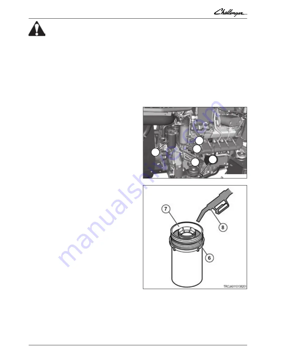
Close the fuel valve (5).

3.

Drain prefilter (2).

4.

Disconnect prefilter water detector

connector (1).

5.

Turn filter element (2) counterclockwise and

remove element from the bracket. Collect

fuel into a applicable container.

6.

Remove the water detector (3) from the

prefilter bottom end.

4

5

2

1

3

TREJA0110063201

GUID-BA2EEB53-E1B3-4D3B-9F43-16A638AB01F2-high.eps [High]

Fig. 3  

7.

Remove the primary filter (4) in an equivalent

procedure.

8.

Connect the water detector (3) to the new

prefilter bottom end.

9.

Lubricate the filter element o-ring seal (6)

with clean fuel.

10.

Fill the outer shell of the filter element (7)

with clean fuel (8).

11.

Turn filter element on the bracket.

12.

Connect the water detector connector (1).

13.

The primary filter (4) is assembled in an

equivalent procedure.

14.

Open the fuel valve

15.

Prime the fuel system.

16.

Start the engine and make sure there are no

leaks.

GUID-764AE0F5-6EA1-4F5A-8ABD-EBA65A7A4869-high.jpg [High]

Fig. 4  

Related Links

Maintenance schedule

 page 1-22

Prime the fuel system

 page 2-218

2. Engine, fuel, and exhaust system

2-8

Rubber Track Tractor

79036240F

Summary of Contents for Challenger MT845E

Page 1: ...Track Tractor MT845E MT855E MT865E MT875E North America 4205 River Green Parkway Duluth GA 30096 USA Challenger is a registered trademark of Caterpillar Inc and is used under license by AGCO AGCO 2019...

Page 2: ...alifornia to cause cancer birth defects or other reproductive harm WARNING Battery posts terminals and related accessories contain lead and lead compounds chemicals known to the State of California to...

Page 3: ...Brake system 5 Compressed air system 6 Hydraulic system 7 Electrical system 8 Cab 9 Air conditioning and heating system 10 Chassis 11 Track belt system 12 Implement drive system 13 Implement lift syst...

Page 4: ...1 11 1 1 24 High pressure lines 1 11 1 1 25 Fluid penetration 1 12 1 1 26 Batteries 1 12 1 1 27 Exhaust fumes 1 13 1 1 28 Noise prevention 1 14 1 1 29 Fire and explosion prevention 1 14 1 1 30 Fire ex...

Page 5: ...1 30 1 9 3 Metric fasteners 1 33 1 10 Dimensions 1 35 1 10 1 Dimensions 1 36 1 11 Shipping weights 1 37 1 12 Machine specifications 1 38 1 12 1 Debris deflectors 1 40 Table of contents 1 2 Rubber Tra...

Page 6: ...al with these situations The safety section does not replace safety practices in other parts of this service manual Practice good safety to help prevent injury or death Learn how to operate the machin...

Page 7: ...rtant safety instructions in the manual GUID 4C201302 DBD2 4BFB 8D98 1DDED263BD6E high jpg High Fig 2 1 1 4 Safety messages The words DANGER WARNING or CAUTION are used with the safety symbol Learn th...

Page 8: ...n injury occurs A person must be alert to possible dangers This person must also have the necessary training skills and tools to do these operations correctly Incorrect operation lubrication maintenan...

Page 9: ...h boxes tools and other loose items that are not a part of the machine Know the appropriate work location hand signals and the personnel that are authorized to give the hand signals Get hand signals f...

Page 10: ...e ground during an electrical storm stay away from the machine 1 1 12 Mount and dismount the machine Mount the machine and dismount the machine only at locations that have steps and or hand holds Befo...

Page 11: ...in neutral and the engine is idling WARNING Do not use ether at any time Use will cause engine damage and or personal injury Do not start the engine until the area is free of personnel to prevent per...

Page 12: ...ailing equipment to align equipment with drawbar Know the maximum dimensions of the machine When operating on icy or muddy roads reduce the travel speed to prevent losing control of machine After oper...

Page 13: ...gloves when touching wire cable When hitting a retainer pin the retainer pin can fly out causing personal injury Make sure that there are no people in the area when hitting a retainer pin To prevent e...

Page 14: ...h a bare hand Remove the filler cap slowly to relieve the pressure The cooling system conditioner contains alkali Alkali can cause personal injury Do not allow alkali to contact skin eyes or mouth GUI...

Page 15: ...ose has a kink Outer coverings have embedded armoring The end fittings are displaced IMPORTANT Take care to contain fluids during the performance of the inspection the maintenance the testing the adju...

Page 16: ...ions can cause an explosion causing an injury Keep open flames or sparks away from the top of the battery Do not smoke in the battery charging areas To prevent an explosion never charge a frozen batte...

Page 17: ...to accumulate on machine Store fuels and lubricants in correctly identified containers away from not approved persons Store rags with oil and any flammable materials in protective containers Do not s...

Page 18: ...operation 1 1 31 Public road transportation Always walk around and visually examine the machine before moving on a public road As a warning to others in the area honk the horn two times before startin...

Page 19: ...CE11A950 high eps High Fig 17 Machine identification Callout Description Serial Number 1 Emissions Control Information N A 2 Machine PIN Plate 3 Engine Serial Number 4 Cab Serial number 5 Operator Sea...

Page 20: ...ence number will start over at the beginning of each model year The first machine of each model year will start with sequence 1001 11 Ending Symbol NOTE For serial number breaks in this manual only th...

Page 21: ...R 2024 Z 2031 Location Built Code definitions Code Definition N Jackson Compliance Region Code definitions Code Definition A Asia Pacific Africa APA E Europe Middle East EME less Russia N North Ameri...

Page 22: ...as food or beverage container s may mislead someone into drinking from them Do not pour or spill waste onto the ground down a drain or into any water source Air conditioning refrigerants escaping into...

Page 23: ...formation is needed 1 5 2 Lubricant viscosities AGCO Genuine Lubricants are the recommended products for this machine Using other lubricants may not provide the same level of required performance Lubr...

Page 24: ...al DEF tank Diesel Exhaust Fluid ISO 22241 AUS 32 See Engine operation and maintenance manual 105 9 liter 28 gal Windscreen Washer Reservoir HFC F 134A 5 0 liter 1 32 gal Refrigerant R134A 1 85 kg 4 9...

Page 25: ...or drain Window washer reservoir fill Window wipers inspect replace Windows clean 1 6 1 Maintenance schedule Initial checks Make sure that all hose clamps on the engine are tight at 10 hours and again...

Page 26: ...e ROPS x 2 Replace the idler and midwheel hub oil x Examine the seat belt x 3 Lubricate the front idler swing link pin 1200 hours or annually that which occurs first Replace the DEF AdBlue pump main f...

Page 27: ...rcooler inspection in a repair workshop x Change the SCR supply module main filter Once a year 5 6 Change the SCR supply module inlet filter Once a year 5 6 Change coolant Every two years 1 or once a...

Page 28: ...guards 1 to get access below the machine 1 TREJA0110115901 GUID AEB9105C B85D 4FDD A295 DC1070EC38EB high eps High Fig 19 2 Remove the bolts and the washers 1 2 3 to get access to the left hand side...

Page 29: ...2 2 Install the bolts and the washers 1 2 3 to install the guards on the left side of the transmission housing 3 2 1 TREJA0110035001 GUID A5C68D43 2532 4D89 9C8E 667C46806BBA high eps High Fig 23 3 In...

Page 30: ...se 1 1 TREJA0110033701 GUID 04BA3FC5 AE22 48C7 8063 8A7E16C3D4FD high eps High Fig 26 1 7 4 Install the engine fan guards NOTE When the words right and left are used it is to refer to the direction th...

Page 31: ...all the bolts to attach the right side engine screen 1 turn the bolts clockwise 1 1 TREJA0110033701 GUID 04BA3FC5 AE22 48C7 8063 8A7E16C3D4FD high eps High Fig 28 1 General 1 28 Rubber Track Tractor 7...

Page 32: ...ars 1 15 forward neutral reverse park 2300 rpm in 16th gear forward 2200 rpm in gears 1 15 forward neutral reverse park 2300 rpm in 16th gear forward 2200 rpm in gears 1 15 forward neutral reverse par...

Page 33: ...ollowing conditions Screw tip 1 extends 6 35 mm 25 in A beyond housing Belleville springs are collapsed nearly flat after screw 2 is tightened to a torque of 11 Nm 8 1 lbf ft GUID 8A45BF90 64A6 4B49 A...

Page 34: ...studs Thread Size Pound Feet lbf ft Newton Meters Nm 1 4 6 8 5 16 13 17 3 8 26 35 7 16 33 45 1 2 48 65 5 8 80 110 3 4 125 170 7 8 190 260 1 300 400 1 1 8 390 525 1 1 4 550 750 1 3 8 700 950 1 1 2 880...

Page 35: ...ng the fitting Tighten after initial tightening as in service work Tighten both the tube and the hose connections finger tight and wrench 1 4 turn O ring fittings must be tightened as for initial asse...

Page 36: ...sembly torque values for metric fasteners Standard High Low Thread Size Pound Feet lbf ft Newton Meters Nm Pound Feet lbf ft Newton Meters Nm Pound Feet lbf ft Newton Meters Nm M6 x 1 8 to 10 9 to 15...

Page 37: ...ft Newton Meters Nm M6 6 8 M8 13 17 M10 26 35 M12 48 65 M16 80 110 M20 125 170 M24 300 400 M30 550 750 M36 880 1200 Metric bolt and cap screws GUID 7AF08829 E556 40A7 B8C7 61E951B65C34 high jpg High F...

Page 38: ...P 68 5 mm 2 70 in C 583 0 mm 23 in Q 1253 0 mm 49 in D 1290 0 mm 51 in R 1330 0 mm 52 36 in E 3400 mm 134 in S 3000 0 mm 118 in F 3630 0 mm 143 in T 2295 0 mm 90 35 in G 5439 0 mm 214 in U 500 mm 19...

Page 39: ...5F 2A88A7CD0787 high jpg High Fig 34 Rear view dimensions A 3325 0 mm 130 9 in D 2985 0 mm 118 in B 2210 0 mm 87 in E 3579 0 mm 141 in C 1376 0 mm 54 in GUID 9432B7A8 1C64 44D7 8BEF 9CA6C2371F98 V2 1...

Page 40: ...dercarriage 24 785 kg 54 642 lb 25 137 kg 55 417 lb With full front and full 64 undercarriage and 16 idler weights 25 010 kg 55 138 lb 25 362 kg 55 913 lb With full front and and full idlers and three...

Page 41: ...urtesy lamps are mounted in the over hang of cab roof Deluxe lighting package consists of standard lighting package in addition to the following lamps Four additional work lamps are mounted on the rea...

Page 42: ...ntrol Category III IVN and category IV Lift capacity 7278 kg 16045 lb 610 mm 24 in Quick hitch hook narrow Cat3 4N Category 4db Cat3 4N Category 5db Quick hitch hook wide Cat4 Cat4 Category 5db Power...

Page 43: ...h Fig 35 Narrow setting 1 2286 mm 90 in and greater gauge setting Compatible with all midwheels at the narrow setting as long as the part plate wear plastic is shifted up Suggested use Gauge setting l...

Page 44: ...ls at the wide setting as long as the part plate wear plastic is shifted down Suggested use All track widths with wide midwheels and within gauge requirements 3 TREJA0110185101 GUID 3324FEDA 062E 4CB8...

Page 45: ...1 General 1 42 Rubber Track Tractor 79036240F...

Page 46: ...Install the charge air cooler 2 98 2 2 21 Remove the air filter assembly 2 106 2 2 22 Install the air filter assembly 2 109 2 2 23 Remove the fan 2 111 2 2 24 Install the fan 2 116 2 2 25 Remove the...

Page 47: ...4 DEF heater circuit fuse 2 261 2 7 5 DEF storage and shelf life 2 261 2 7 6 Low diesel exhaust fluid DEF level 2 262 2 8 Fluid specifications 2 264 2 8 1 Oil specification 2 264 2 8 2 Fuel specifica...

Page 48: ...3 2 Engine output depending on fuel quality 2 306 2 14 Tightening torques 2 307 2 15 Special tools 2 309 2 15 1 Engine lifting tools 2 309 2 15 2 Cylinder block tools 2 309 2 15 3 Timing gear and flyw...

Page 49: ...ve the crankshaft 2 364 2 21 2 Do a check for the crankshaft 2 365 2 21 2 1 Rework instructions for the crankshaft 2 366 2 21 3 Replace the crankshaft gears 2 367 2 21 4 Install the crankshaft 2 368 2...

Page 50: ...rgers with the mounting bracket 2 404 2 28 10 Install the low pressure turbochargers with the mounting bracket 2 405 2 28 11 Removing the turbocharger 2 406 2 28 12 Checking the turbocharger 2 406 2 2...

Page 51: ...the SM lifting capacity test is OK 2 438 2 30 9 SPN 4090 FMI 16 SPN 521025 FMI 31 SPN 521026 FMI 31 2 439 2 30 9 1 Cleanup of the SCR catalyst 2 441 2 30 9 2 Make the dosing rate test 2 442 2 30 9 3...

Page 52: ...5 45C2 A0DE 0AFFD88AC08F high jpg High Fig 1 4 Replace the air filter element 1 with a new element if damaged 5 Replace the air filter element if the gaskets are damaged or missing 6 Replace the air f...

Page 53: ...1 Clean the fuel filters and adjacent area 2 Close the fuel valve 5 3 Drain prefilter 2 4 Disconnect prefilter water detector connector 1 5 Turn filter element 2 counterclockwise and remove element f...

Page 54: ...E The battery disconnect switch is shown in the off position GUID 57C975DA BFD1 4013 AE90 52262183416A high jpg High Fig 5 3 Remove the battery disconnect switch key 1 GUID 413DAA31 908C 454D B08A 596...

Page 55: ...bar into the square drive 1 of the fan drive belt tensioner 2 Push clockwise and remove the fan drive belt 3 from the pulleys Slowly release the fan drive belt tensioner to the neutral position Remov...

Page 56: ...the pulleys 5 Slowly release the fan drive belt tensioner to the neutral position 6 Remove the breaker bar GUID DC31FAE0 926B 4E37 9BD9 3052929ED9E2 high jpg High Fig 11 7 Install the right hand fan g...

Page 57: ...omponents can burn Severe personal injury can result Let the engine and components cool before doing maintenance Procedure 1 Park the machine on a solid level surface Stop the engine apply the parking...

Page 58: ...and the left hand fan guard 2 GUID 3978DDBE 5060 43F8 861E BFF8A5CE3C04 high jpg High Fig 19 6 WARNING Equipment or parts under spring tension can cause bodily injury Use caution in releasing belt ten...

Page 59: ...stall the accessories belt 3 to the pulleys Slowly release the accessories belt tensioner to the neutral position Remove the breaker bar GUID DF4CCF4E 4F91 4490 B6F7 E4C5FEB25DD9 high jpg High Fig 21...

Page 60: ...onents can burn Severe personal injury can result Let the engine and components cool before doing maintenance Procedure 1 Park the machine on a solid level surface Stop the engine apply the parking br...

Page 61: ...This as a preview PDF file from best manuals com Download full PDF manual at best manuals com...

Reviews: