background image

27

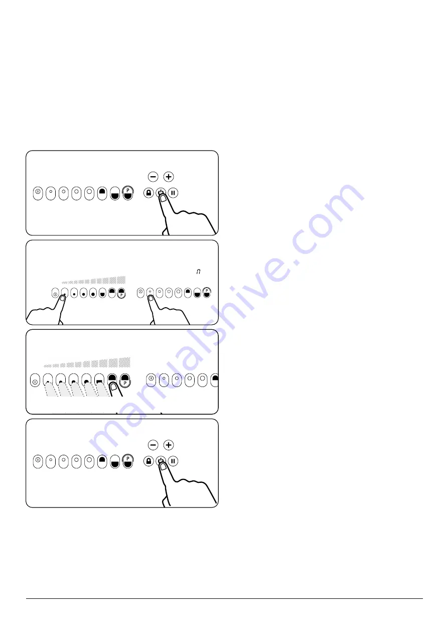
Bridge Function

The bridge function allows both cooking zones/elements 

to be switched on at the same time and controlled as one 

cooking zone only.
This is ideal for an induction caompatible griddle or fish kettle 

for example.

Step 1. 

Touch the power button.

1 2 3 4 5 6 7 8

U

1 2 3 4 5 6 7 8

Step 2. 

Activate by selecting both cooking elements 

simultaneously.

1 2 3 4 5 6 7 8

9

Step 3. 

Set the required power level by the left slider only.

Please note

: Setting the power level is only possible by 

the left slider.

Step 4. 

To switch off touch the standby.

Summary of Contents for R3 100-4i

Page 1: ...llation Instructions CAUTION THIS UNIT IS HEAVY PROPER EQUIPMENT AND ADEQUATE MANPOWER MUST BE USED IN MOVING THE RANGE TO AVOID DAMAGE TO THE UNIT OR THE FLOOR REMEMBER when replacing a part on this...

Page 2: ...ul to make a note of your AGA appliance Serial Number when it is being installed The serial number can be found on the rear of the appliance My AGA Details Serial No AGA Service No AGA Dealer or store...

Page 3: ...an Oven Model 160 5i 16 12 2 zone induction hotplate 20 13 Oven shelves 28 14 AGA accessories 30 15 Conventional fan oven accessories 160 5i model only 32 16 Cleaning Caring 33 17 Maintenance 34 18 In...

Page 4: ......

Page 5: ...the pan more than one third fill of fat or oil n Installation and maintenance must be performed by a qualified installer or service agency n WARNING This appliance must be installed with an appropriat...

Page 6: ...ful if inhaled May be irritating to skin eyes nose and throat When handling avoid contact with skin or eyes Use disposable gloves face masks and eye protection After handling wash hands and other expo...

Page 7: ...ce operation of the warranty and could affect your statutory rights In the interests of safety and effective use please read the following before using your new AGA appliance Ensure that the kitchen i...

Page 8: ...Lower oven BAKE SIMMER E Warming oven F Infrared Grill G Simmering and Boiling Plate H Resting plate I Induction Hotplate J Warming oven switch A C B D E F J I This model illustrate 100 4i This model...

Page 9: ...g plate F Top Oven Roast G Infrared Grill H Warming Oven I Lower Oven Bake Simmer J Simmering and Boiling Plate K Top plate and resting area L Induction Hotplate M Simmering Plate L This model illustr...

Page 10: ...ws individual control of ovens and hotplates There is also a high speed infrared grill If desired individual functions such as hotplates and ovens can be turned off or on even down to the e setting to...

Page 11: ...ppearance of a classic AGA heat storage enamelled cast iron cooker However it s flexibility is almost unbounded because in place of a single heat source each cooking zone has its own electrically heat...

Page 12: ...ended Any stubborn stains can be removed with the wire brush supplied The lower BAKE SIMMER WARMING oven and GRILL compartments are enamelled and do not need to be seasoned General advice Food should...

Page 13: ...can be protected by the use of the cold plain shelf or shielded by means of the large roasting tin which means you can cook food that requires different temperatures at the same time If food is brown...

Page 14: ...table for stuffed meat and stuffed poultry Make sure that pork and poultry reach an internal temperature of at least 75 C Always bring soups casseroles and liquids to the boil before putting in the si...

Page 15: ...en will reduce to a simmer temperature The cast iron upper oven is ideal for baking especially when baking is required over longer periods for example ideal for fruit cakes PLEASE NOTE If you wish to...

Page 16: ...lease Note when the grill is in use the power is cut to the ovens Normal grilling unless for very long periods will not affect the heat retention in the ovens If cooking in the ovens at the same time...

Page 17: ...ntrols The boiling plate setting Fig 9 1 heat up time approx 35 mins 40 mins The hottest setting the boiling plate setting is used for boiling grilling stir frying making toast indeed anything that re...

Page 18: ...st iron resting plates as they are heavy Ensure they are cold before removing Removing resting plates Insert lifting tool Fig 9 3 in recess at rear of resting plate Lift up at rear then slide out care...

Page 19: ...f oven Victoria sandwich fruitcake traybakes and cheesecake Lower Baking Oven 1st runner Whisked sponges some biscuits and small cakes 2nd runner Baked fish souffl s shepherd and cottage pie lasagne V...

Page 20: ...the shelf will pass under the shelf stop and then pull the shelf forward Fig 11 4 To refit the shelf line up the shelf with a groove in the oven side and push the shelf back until the ends hit the sh...

Page 21: ...oven depth 321mm 125 8 by width 289mm 11 3 8 in the tall oven When the oven is on DO NOT leave the door open for longer than necessary otherwise the knobs may get very hot Always leave a finger s wid...

Page 22: ...190 C for 20 minutes then 160 C 150 C for remainder Do not forget to include the weight of the stuffing For fresh or frozen prepacked poultry follow instructions on the pack Thoroughly thaw frozen po...

Page 23: ...oven it complements the boiling plate on the right hand side Fig 11 9 For simmer plate temperature guide please refer to table opposite Time mins Approximate temperature with lid down 5 mins 65 C 70 C...

Page 24: ...area Smaller pans will take longer to heat Using a pan with a lid will help pan contents boil more quickly Ideally pans should have near flat bottoms to maximise induction efficiency Most types of pan...

Page 25: ...eat Protection Power levels will be automatically reduced if excessive high temperatures are monitored below the cooking zone If high temperatures are detected it will not be possible to adjust the po...

Page 26: ...switch off Step 3 Touch the first power level pad to select warming level one Step 4 To select the second warming level touch and hold the first power level Step 5 To select the third warming level t...

Page 27: ...1 Kitchen Timer for general kitchen timing requirements for example timing food cooked in an oven 2 Minute Minder for timing the duration of the induction cooking process Step 1 To switch on touch the...

Page 28: ...ng the or 0 to cancel After the set time has elapsed and alarm will sound To cancel touch the power off pad 001 Step 1 To switch on touch the standby 888 Step 2 Press the and button together Step 4 If...

Page 29: ...ep 2 Touch the induction on If power level is not set within 20 seconds the unit will automatically switch off Step 3 Set the required power level 1 2 3 4 5 A 6 7 8 9 001 Step 4 Press the and button t...

Page 30: ...n If power level is not set within 20 seconds the unit will automatically switch off 1 2 3 4 5 6 7 8 9 Step 3 Set the required power level Step 3 Touch the lock Step 4 Touch the lock to reset power le...

Page 31: ...uction caompatible griddle or fish kettle for example Step 1 Touch the power button 1 2 3 4 5 6 7 8 U 1 2 3 4 5 6 7 8 Step 2 Activate by selecting both cooking elements simultaneously 1 2 3 4 5 6 7 8...

Page 32: ...28 13 Oven shelves Fitting the shelves for cast iron roast oven Removing the shelves for cast iron roast oven DESN 512403 DESN 512405 DESN 512404 DESN 512406 Fig 13 1 Fig 13 3 Fig 13 2 Fig 13 4...

Page 33: ...ng and grill Fitting and removal of shelves These shelves are designed to slide out Note Shelf slides out to stop position DESN 511867 DESN 511866 Fig 13 5 Fig 13 6 STOP ON SHELF MUST PROJECT UPWARDS...

Page 34: ...he roasting tin can be used with the grill rack in its high position for grilling at the top of the roasting oven It can be used for roasting meat or poultry with or without the grill rack 1 x half si...

Page 35: ...toaster direct onto the plate with the handle at an angle from the handle of the cover Close the cover and wait for the bread to toast one side this will take 1 2 minutes dependent upon the variety o...

Page 36: ...nly When using the tall oven you can cook on all four shelves at the same time but make sure that they are well spaced out to allow the hot air to circulate ArtNo 324 0002 Oven shelf ArtNo 324 0010 Pl...

Page 37: ...anything containing acid is spilt on the enamel wipe off immediately Clean off any condensation streaks on the front plate around the oven doors or vitreous enamel maybe permanently discoloured Remem...

Page 38: ...appliance MUST only be maintained and installed by a qualified engineer AGA engineer or an authorised distributor DO NOT alter or modify the appliance Spare Parts To maintain optimum and safe perform...

Page 39: ...n instructions DO NOT store or use gasoline or other flammable vapors and liquids in the vicinity of this or any other appliance Installation and service must be performed by a qualified installer or...

Page 40: ...in walls or floor Electrical wires may be behind the wall or floor covering and could cause an electrical shock if you touch them Locate any electrical circuits that could be affected by the installat...

Page 41: ...red for the body of the appliance should be increased overall by 10 mm beyond the figures quote above This allows safe margin to take into account the natural dimensional variations found in major cas...

Page 42: ...for the body of the appliance should be increased overall by 10 mm beyond the figures quote above This allows safe margin to take into account the natural dimensional variations found in major casting...

Page 43: ...less than 60mm horizontally from the appliance Fig 21 2 Fig 21 4 Surfaces over the top of the appliance must not be closer than 650mm i e cabinets or cookerhoods The rear gap at the rear of the applia...

Page 44: ...s fitted with 25 mm spacer brackets This allows the appliance to be fitted where the rear wall is constructed of combustible materials such as all timber or stud wall partitions and batoned plasterboa...

Page 45: ...t must be replaced by the manufacturer its service agent or similarly qualified person to avoid a hazard For the cooker A 1PH 13 AMP 230V or 3PH 400V minimum 16A per phase 50 Hz fused electrical suppl...

Page 46: ...appliance is designed for the voltage stated on the rating plate which is situated behind the plinth cover n If the supply cord is damaged it must be replaced by the manufacturer its service agent or...

Page 47: ...spanner feet can be adjusted at front to make FINE adjustments to the front of the appliance and to provide a brake for the wheels Fig 24 3 7 Turning the bolt clockwise will lower the wheel thus incr...

Page 48: ...ARE LOCATED IN FRONT GUIDE BRACKET DESN 517772 1 To install the conventional oven module raise the top plate by undoing the 4 hob nuts 2 Adjust the height to suit the main cooker 3 Lock in at the rear...

Page 49: ...ESN 517654 DESN 517654 Control Knob Location Ensure control knobs are located onto spindles correctly as shown in Fig 25 1 Handrail Location Locate handrail onto spindle lock into position with grub s...

Page 50: ...0W 225 178 192 110 B31 B11 32 12 1 2 2 1 600W 300W 1 2 3 4 600W 300W 1 3 4 2 11 12 L E N R1 R0 R6 R4 N N L L 365 B31 B21 B11 32 22 12 12 200 c 350 c P3 P4 P5 P6 1 2 7 6 5 1000W 1 2 HOT PLATE P3 P2 P1...

Page 51: ...de Colour b Blue br Brown bk Black or Orange r Red v Violet w White y Yellow g y Green yellow gr Grey Code Description A1 13 AMP Mains Fused Connection B1 Terminal Strip C1 Component Overheat Thermost...

Page 52: ...1 A1 B1 Br E1 11 P 12 1 1 2 B G Y E N2 Code Colour b Blue br Brown bk Black or Orange r Red v Violet w White y Yellow g y Green yellow gr Grey Code Description A1 Hotplate Selector Switch B1 Hotplate...

Page 53: ...Notes 49...

Page 54: ...Notes 50...

Page 55: ...Notes 51...

Page 56: ...change specifications and make modifications to the appliances described and illustrated at any time www agaliving com www agacookshop co uk Manufactured By AGA Rangemaster Station Road Ketley Telfor...

Reviews: