background image

31

INSTALLATION

Check the appliance is electrically safe and gas sound when you have finished.

Flexible hose

Pipework

Pipework

Flexible hose

675

A

315

Gas inlet

470

350

All dimensions in millimetres

Gas Connection

This must be in accordance with the relevant standards.
The flexible hose (not supplied with the cooker) must be 

in accordance with the relevant standards. Hoses may be 

purchased at most builders’ merchants.

In the UK, we recommend that a Micropoint gas hose is 

used when installing this appliance.

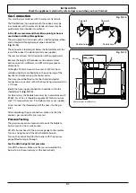
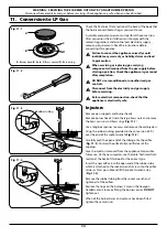
The gas supply must terminate with a side facing pipe-elbow 

and a downward facing bayonet-pipe-connection  

(

Fig. 10.14

).

The connector is located just below the hotplate level at the 

rear of the cooker. If in doubt contact your supplier.
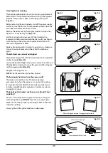
The rear cover boxes limit the position of the supply point.
Because the height of the cooker can be adjusted and 

each connection is different, it is difficult to give precise 

dimensions.
Although a 900 mm hose can be used, a 1250 mm hose 

will allow slightly more flexibility in the positioning of the 

bayonet and make moving the cooker easier.
The hose should be fitted so that both inlet and outlet 

connections are vertical so that the hose hangs downwards in 

a ‘U’ shape.
Ideally the hose supply connection should be within the 

shaded area ‘A’ 

(Fig. 10.15)

.

For Natural Gas, the flexible hose must be in accordance with 

BS 669. For LP Gas, it should be capable of 50 mbar pressure 

and 70 °C temperature rise. If in doubt contact, your supplier.
Screw connect the threaded end of the hose into the gas 

inlet.
After completing the gas connection, make sure that the 

cooker is gas sound with a pressure test.

Pressure Testing

The gas pressure can be measured at one of the hotplate 

burner injectors (not a wok burner).
Lift off a burner head. Fit the pressure gauge to the injector. 

Turn on and light one of the other hotplate burners.
Turn on the control knob for the burner with the pressure 

gauge fitted to let gas through.

See the data badge for test pressures.

Turn off the burners. Make sure that you reassemble the 

burner top in the correct way on the burner body.

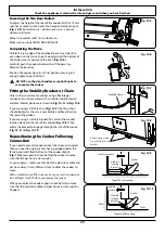
Fig. 10.14 

Fig. 10.15 

Summary of Contents for MASTERCHEF DELUXE 90 DUAL FUEL

Page 1: ...USER GUIDE INSTALLATION INSTRUCTIONS MASTERCHEF DELUXE 90 DUAL FUEL U111083 02...

Page 2: ...tbread from the oven allow to cool for 5 minutes then remove to a cooling rack Cool for 10 minutes 5 Drizzle the chocolate over the cooled shortbread or pipe in a zigzag fashion as shown Let the choco...

Page 3: ...s 20 The Griddle optional extra 20 Glide out Grill 21 Control Panel and Doors 21 Ovens 22 Cleaning Table 23 9 Troubleshooting 24 10 Installation 26 Dear Installer 26 Safety Requirements and Regulation...

Page 4: ...ii...

Page 5: ...or liability claim Before operating the ovens please refer to the oven shelf installation in the Accessories section WARNING The appliance and its accessible parts become hot during use and will reta...

Page 6: ...re correctly fitted and that the terminal screws are tight Secure the mains cable using the cable clamp Minimum temperature rating T105 Read the instructions before installing or using this appliance...

Page 7: ...to 200 C and run for at least an hour Before using the grill for the first time you should also turn on the grill and run for 30 minutes with the grill pan in position pushed fully back and the grill...

Page 8: ...steam burst when the oven door is opened Fig 1 3 When opening the oven stand well back and allow any steam to disperse NEVER operate the cooker with wet hands DO NOT use a towel or other bulky cloth i...

Page 9: ...en the oven is on DO NOT leave the oven door open for longer than necessary otherwise the control knobs may become very hot DO NOT use the timed oven if the adjoining oven is already warm DO NOT place...

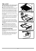
Page 10: ...t Grill Glide out Grill Care n WARNING Unattended cooking under the grill can be dangerous and may result in fire When using the grill make sure that the grill pan is in position and pushed fully in o...

Page 11: ...ts the flow of gas if the flame goes out When a hotplate control knob is pressed in sparks will be made at every burner this is normal Do not attempt to disassemble or clean around any burner while an...

Page 12: ...performance and could damage the pan supports You should also avoid using unstable and misshapen pans that may tilt easily and pans with a very small base diameter e g milk pans single egg poachers F...

Page 13: ...amber and preheat the appropriate part s of the grill for two minutes The grill trivet can be removed and the food placed on it while you are waiting for the grill to preheat 2 Do not leave the grill...

Page 14: ...sisted and conventional cooking These functions should be used to complete most of your cooking The browning element and base heat can be used in the latter part of the cooking process to fine tune th...

Page 15: ...emperature by approximately 10 C for recipes previously cooked in a conventional oven If you wish to preheat the oven wait until the indicator light has gone out before inserting the food Fanned Grill...

Page 16: ...on Oven The multi function oven has two controls a function selector and a temperature setting knob Fig 2 11 Turn the function selector control to a cooking function Turn the oven temperature knob to...

Page 17: ...rs 1 Slide the shelf out on the runners While holding one of the runners securely carefully lift the rear of the shelf upwards the shelf will spring clear of the central restraining tab Repeat for the...

Page 18: ...ch on both elements Fig 3 1 Fig 3 2 To switch on the right half element Fig 3 3 Fig 3 4 Fig 3 5 Cooking suggestions 1 Nearest to the element Toast streaky bacon 2 Middle high cheese on toast welsh rar...

Page 19: ...Please take care when inserting or removing the oven probe Use oven gloves The clock will change to display the current temperature of the probe and the intended stop temperature Fig 4 2 The stop tem...

Page 20: ...on 5 3 button clock Minute Minder Setting the minute minder Note The cook symbol remains visible during normal operation Note The cook symbol remains visible during normal operation Note The cook symb...

Page 21: ...on ArtNo 306 0001 3 button clock Alarm will sound when cooking has finished press any button to stop the alarm If the alarm is not stopped it will stop automatically after 7 minutes Set the length of...

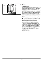
Page 22: ...Other containers should be placed centrally Keep all trays and containers away from the back of the oven as overbrowning of the food may occur For even browning the maximum recommended size of a bakin...

Page 23: ...0 C 150 C for remainder Do not forget to include the weight of the stuffing For fresh or frozen pre packed poultry follow instructions on the pack Thoroughly thaw frozen poultry before cooking Cassero...

Page 24: ...e replacing them n DO NOT put the burner heads in a dishwasher When replacing a burner head make sure that it locates properly within the base Fig 8 1 If you look at the bottom of the burner head you...

Page 25: ...ach side Fig 8 4 For each side support the side rail with one hand and with the other hand lift the frame up and out of the side clips Fig 8 5 For safety push the side rails back into the grill chambe...

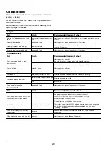
Page 26: ...ated at 200 C for about one hour This will make sure that the Cook Clean panels are working effectively n DO NOT use steel wool oven cleaning pads or any other materials that will scratch the surface...

Page 27: ...cloth supermarket Sides and plinth Painted surface Hot soapy water soft cloth Splashback rear grille Enamel or stainless steel Hot soapy water soft cloth Cream cleaner with care if necessary Control...

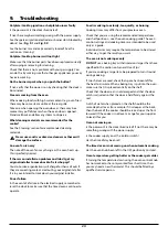
Page 28: ...re in the electrical supply remember to reset the clock to make sure that the timed oven continues to operate Food is cooking too slowly too quickly or burning Cooking times may differ from your previ...

Page 29: ...adjusted to alter its angle Fig 9 5 Loosen the bottom hinge fixing screws and use the notch and a flat bladed screwdriver to move the position of the hinge to set the hinge position Fig 9 6 Retighten...

Page 30: ...stallation and Use regulations The relevant Building IEE regulations In the Republic of Ireland the cooker must be installed in accordance with The installation must be carried out by a competent pers...

Page 31: ...tify the gas type for which the appliance is now set You will need the following equipment to complete the cooker installation satisfactorily Stability bracket If the cooker is to be supplied with gas...

Page 32: ...o any material that de laminates or discolours at temperatures less than 65 C above room temperature DO NOT box the cooker in it must be possible to move the cooker in and out for cleaning and servici...

Page 33: ...pace to get behind it n DO NOT use the door handles or control knobs to manoeuvre the cooker Fitting the Stability Bracket or Chain Unless otherwise stated a cooker using a flexible gas connector must...

Page 34: ...le Fig 10 12 and screw in the M5 screws Fig 10 13 Levelling You are recommended to use a spirit level on a shelf in one of the ovens to check for level Place the cooker in its intended position taking...

Page 35: ...n be used a 1250mm hose will allow slightly more flexibility in the positioning of the bayonet and make moving the cooker easier The hose should be fitted so that both inlet and outlet connections are...

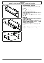
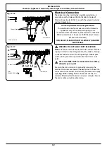
Page 36: ...THE APPLIANCE MUST BE EARTHED Note The cooker must be connected to the correct electrical supply as stated on the voltage label on the cooker through a suitable cooker control unit incorporating a do...

Page 37: ...the inside of the outer plinth onto the 2 screws Fig 10 19 Note To aid the fitting of the outer plinth we advise that you open the doors and place the wings of the outer plinth over the side panels a...

Page 38: ...appliance is electrically safe Injectors Remove pan supports and burner heads Remove burner heads Undo the large brass nuts and remove the brass venturis and brass rings Fig 11 1 Use a long box spann...

Page 39: ...care not to damage or strain the wiring Turn the bypass screw on each control clockwise to the stop Fig 11 7 Stick on Label Stick the LP gas label over the natural gas part of the appliance data labe...

Page 40: ...Description X01 Grill Front Switch X02 Grill Energy Regulator X03 Left Hand Grill Element X04 Right Hand Grill Element X05 Left Hand Oven Thermostat X06 Left Hand Oven Multifunction Switch X07 Left Ha...

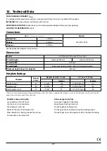
Page 41: ...0mm Hotplate Ratings Hotplate Bypass Screw Natural Gas G20 20 mb L P Gas 29 37 mb Injector Injector Centre burner 57 5 0 kW 165 5 0 kW 364g h 107 Large burner 40 3 0 kW 120 3 0 kW 218g h 82 Semi Rapid...

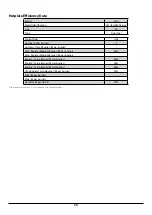
Page 42: ...as burner Semi Rapide Medium Burner EE gas burner 60 Semi Rapide Medium Burner EE gas burner Rapide Large Burner EE gas burner 58 Rapide Large Burner EE gas burner 58 Rapide Large Burner EE gas burner...

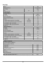
Page 43: ...ght hand Efficiency Fuel type Electric Cavity type Fanned Power conventional Power forced air convection 2 5 Volume Litres 67 Energy consumption electricity conventional kWh cycle Energy consumption e...

Page 44: ...40 NOTE...

Page 45: ...41 NOTE...

Page 46: ...42 NOTE...

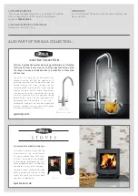
Page 47: ...delivering great design outstanding functionality and in recent years cutting edge technology Now the range has been extended to take in a collection of innovative kitchen taps 4 IN 1 TAP COLLECTION...

Page 48: ...and Wales Registration No 354715 Registered Office Meadow Lane Long Eaton Nottingham NG10 2GD AGA continuously seeks improvements in specification design and production of products and thus alteratio...

Reviews: