AGA ECG Standard, Installation, Servicing And User Operating Instructions
AGA ECG Standard is a cutting-edge product designed for professional installation, servicing, and user operations. Our comprehensive manual, available for free download at manualshive.com, provides clear and concise instructions to ensure seamless setup and efficient utilization. Discover the full potential of AGA ECG Standard with our user-friendly manual!
Share
Download


Reviews:
No comments
Related manuals for ECG Standard
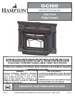
GCI60
Brand: HAMPTON BAY Pages: 18

OSAKA
Brand: Panadero Pages: 20

C07788
Brand: deville Pages: 52

M48590
Brand: Carolina Cooker Pages: 17

bemodern
Brand: Daytona Pages: 4

ANGELA
Brand: Extraflame Pages: 36

NORIS
Brand: Extraflame Pages: 40

FIANDRA IDRO
Brand: Extraflame Pages: 36

Vue Portrait
Brand: F2 Fires Pages: 20

highlander 7 solo
Brand: Dunsley Heat Pages: 4

Hasvik 231.17 ST
Brand: Haas+Sohn Pages: 2

AQUA 187.19-WT
Brand: HAAS + SOHN Pages: 8

KING KE1107
Brand: Blaze King Pages: 57

RAIS 106
Brand: RAIS Pages: 13

1600S
Brand: Seefire Pages: 10

SKV2B
Brand: Vigan Mammoth Pages: 20

H11
Brand: NESTOR MARTIN Pages: 77

AP5613
Brand: Ashley Pages: 56


