


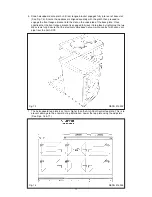

4. Run a straight edge along the front of the AGA Dual Control plinth, to ensure the front face
of both plinths sit squarely against the straight edge. (See Fig. 13)
When satisfied both plinths sit squarely, jacking screws can be tightened until they just make
contact with the AGA Dual Control plinth, and locking screws can now be tightened.
Fig. 13
DESN 516551
USE STRAIGHT EDGE ACROSS BOTH PLINTHS TO ENSURE PLINTHS
ARE ALIGNED SQUARELY
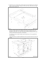
Fig. 14
DESN 516553
16
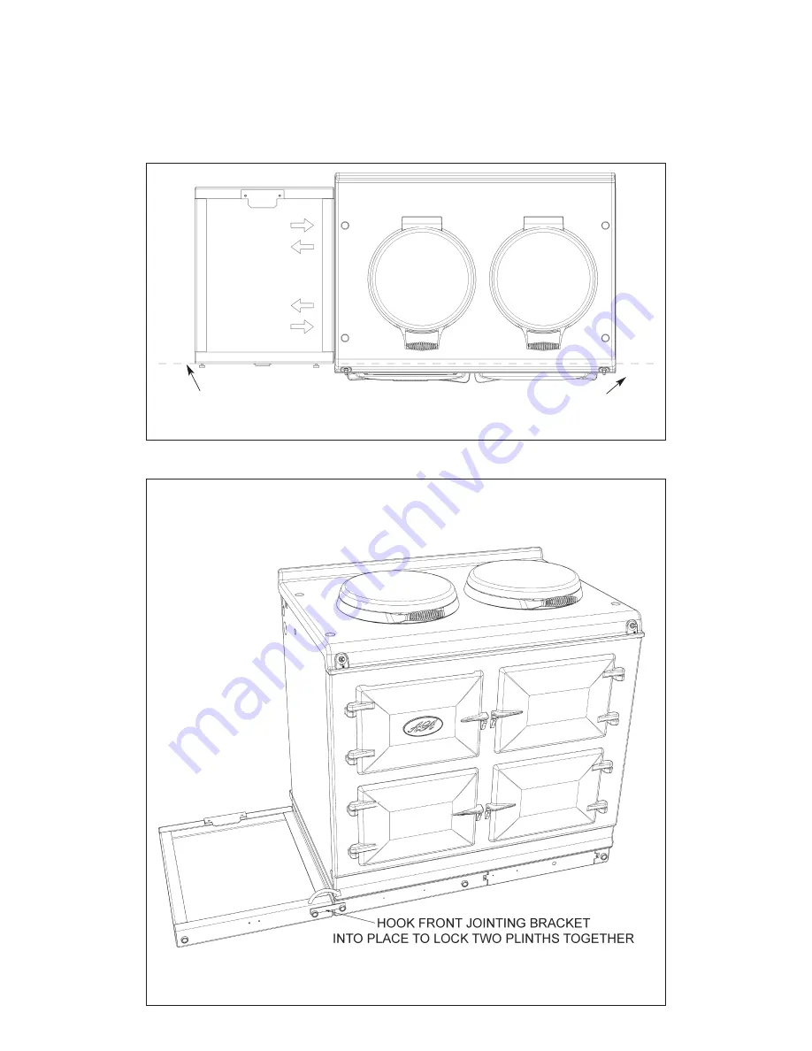
5. Front jointing bracket can now be hooked into place over the two pot magnets. This will latch
the two plinths together. (See Fig. 14)
Summary of Contents for DC3
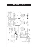
Page 20: ...WIRING DIAGRAM AGA DC3 20 Fig 20 ...
Page 23: ...23 ...


