8
POWER SUPPLY - AGA DC3
WARNING: THIS APPLIANCE MUST BE EARTHED.
THIS APPLIANCE IS DESIGNED FOR THE VOLTAGE STATED ON THE RATING PLATE,
WHICH IS SITUATED BEHIND THE PLINTH COVER.
A 1PH 32 amp 230V or 3PH 400V minimum 16A per phase ~ 50 Hz fused electrical supply is
required adjacent to the appliance. External wiring to the unit must be installed using the mains
cable provided, in accordance with the current wiring regulations and any local regulations which
apply. If cable is shortened, new ferrules must be fitted to the stripped conductors.
The method of connection to the mains electricity supply must facilitate complete electrical
isolation of the appliance, by a multi-pole switch, having a contact separation of at least 3mm on
all poles.
The isolator should not be positioned immediately above the cooker, but must be fitted within 2
metres of the appliance.
The isolator maybe separate from the connection point.
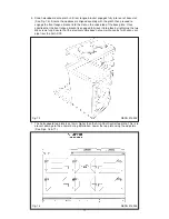
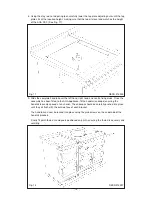
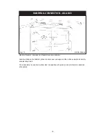
The mains connection point must be accessible within the areas shown in Fig 4A, Page 9 for
cable routing options.
For 2 or 3 phase installations an optional adaptor kit must be obtained (Part No. AE4M231226).
POWER SUPPLY - HOTCUPBOARD (AGA DC5)
THE HOTCUPBOARD ATTACHMENT REQUIRES AN INDEPEDENT SINGLE PHASE
POWER SUPPLY.
WARNING: THIS APPLIANCE MUST BE EARTHED.
THIS APPLIANCE IS DESIGNED FOR THE VOLTAGE STATED ON THE RATING PLATE,
WHICH IS SITUATED ON A SLIDE-OUT TRAY IN THE HOTCUPBOARD BASE PLATE
ABOVE THE PLINTH.
A 230v ~ 50 Hz, 3 amp fused electrical supply is required adjacent to the appliance. External
wiring to the unit must be installed using a 3 core silicon - SIHF insulation cable and in
accordance with the current wiring regulations and any local regulations which apply.
The method of connection to the mains electricity supply must facilitate complete electrical
isolation of the appliance, preferably by a fused double pole switch, having a contact separation
of at least 3mm in both poles.
The isolator should not be positioned immediately above the appliance, but must be fitted within
2 metres of the appliance.
Summary of Contents for DC3
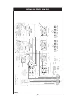
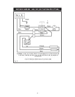
Page 20: ...WIRING DIAGRAM AGA DC3 20 Fig 20 ...
Page 23: ...23 ...


