background image

18

INSTALLATION

Check the appliance is electrically safe and gas sound when you have finished.

Gas Connection

Installation of this range must conform with local codes or, in 

the absence of local codes, with the National Fuel Gas Code, 

ANSI Z223.1-latest edition.

In Canada

The range must be installed in accordance with the current 

CGA Standard CAN/CGA-B149 – Installation Codes for Gas 

Burning Appliances and Equipment and/or local codes.

In The Commonwealth Of Massachusetts

This product must be installed by a licensed plumber or 

gas fitter when installed within the Commonwealth of 

Massachusetts.
A “T” handle type manual gas valve must be installed in 

the gas supply line to this appliance, in an easily accessible 

location, outside the range. This is for the purpose of easily 

turning on or shutting off the gas supply to the appliance.

Gas Supply Requirements
Provide Adequate Gas Supply

Before installation, ensure that the local distribution 

conditions (nature of the gas and gas pressure) and the 

adjustment of the appliance are compatible.
The range is designed to operate at a manifold pressure of 5’’ 

of water column (1.25 kPa) on natural gas. A conversion kit for 

LP gas (Propane) is supplied with the range. When converted 

to LP gas, a pressure of 10’’ of water column (2.49 kPa) is 

required.
Make sure you are supplying your range with the correct type 

of gas.
If the range is to be used on LP gas, a qualified LP installer 

must convert it. We recommend that the range be converted 

before installation. This must be done before the range can 

be used on LP gas.
For proper operation, the pressure of natural gas supplied to 

the regulator must be between 4½’’ and 13’’ of water column 

(1.12–3.24 kPa).
For LP gas, the pressure supplied must be between 10’’ and 

13’’ of water column (2.49–3.24 kPa).
When checking for proper operation of the regulator, the 

inlet pressure must be at least 1’’ (0.25 kPa) greater than the 

operating (manifold) pressure as given above.
The pressure regulator located at the inlet of the range 

manifold must remain in the supply line regardless of 

whether natural or LP gas is being used.
A flexible metal appliance connector used to connect the 

range to the gas supply line should have an I.D. of ½’’ and be 

5 feet in length for ease of installation.

Connect the Range to the Gas Supply

Shut off the main gas supply valve before disconnecting the 

old range and leave it off until the new hookup has been 

completed. Don’t forget to relight the pilot on other gas 

appliances when you turn the gas back on.

Because hard piping restricts movement of the range, the 

use of a CSA International-certified flexible metal appliance 

connector is recommended unless local codes require a hard-

piped connection.
Never use an old connector when installing a new range. 

If the hard piping method is used, you must carefully align 

the pipe; the range cannot be moved after the connection is 

made.
To prevent gas leaks, put pipe joint compound on, or wrap 

pipe thread tape with Teflon* around, all male (external) pipe 

threads.

A. 

Install a manual gas line shut-off valve in the gas line in 

an easily accessed location outside of the range. Make 

sure everyone operating the range knows where and 

how to shut off the gas supply to the range.

B. 

Install a male ½’’ (1.5 cm) flare union adapter to the ½’’ 

(1.5 cm) NPT internal thread elbow at inlet of regulator. 

Use a backup wrench on the regulator fitting to avoid 

damage. 

C. 

Install male ½’’ (1.5 cm) or ¾’’ (2 cm) flare union adapter 

to the NPT internal thread of the manual shut-off valve, 

taking care to backup the shut-off valve to keep it from 

turning.

D. 

Connect flexible metal appliance connector to the 

adapter on the range. Position the range to permit 

connection at the shut-off valve.

E. 

When all connections have been made, make sure 

all range controls are in the off position and turn on 

the main gas supply valve. Use a liquid leak detector 

at all joints and connections to check for leaks in the 

system. Use a product specifically manufactured for 

leak detection. Leak testing of the appliance shall 

be conducted in accordance to the manufacturer’s 

instructions.

n

DO NOT use a flame to check for gas leaks.

When using test pressures greater than ½ psig (3.5 kPa) 

to pressure test the gas supply system of the residence, 

disconnect the range and individual shut-off valve from 

the gas supply piping. When using test pressures of ½ psig 

(3.5 kPa) or less to test the gas supply system, simply 

isolate the range from the gas supply system by closing the 

individual shut-off valve.

Flexible Connector

Installer

: Inform the consumer of the location of the gas 

shut-off valve.

Seal the Openings

Seal any openings in the wall behind the range and in the 

floor under the range when hookups are completed.

IMPORTANT:

 When all connections are completed make 

sure the flow of combustion and ventilation air to the range 

is unobstructed.

Summary of Contents for APRO48AGSS

Page 1: ...User Guide Installation and Service Instructions U110588 01 APRO48AGSS 48 All Gas...

Page 2: ...om a neighbor s phone Follow the gas supplier s instructions If you cannot reach your gas supplier call the fire department Installation and service must be performed by a qualified installer service...

Page 3: ...ls 12 Cooktop Burners 12 Griddle 13 Control Panel and Oven Doors 13 6 Troubleshooting 14 7 Installation 16 Regulations 16 For Your Safety 16 Installation Safety Instructions 16 Converting to Propane G...

Page 4: ...iv...

Page 5: ...cooktop The hot air from an oven vent may ignite flammable items and may increase pressure in closed containers which may cause them to burst Many aerosol type spray cans are EXPLOSIVE when exposed t...

Page 6: ...California to cause cancer or reproductive harm and requires businesses to warn customers of potential exposures to such substances This appliance contains or produces a chemical or chemicals which c...

Page 7: ...affect the durability of the enamel and may be cleaned off with a metal polish Ovens n n Take care when opening the door n n Let hot air and steam escape before removing or replacing food n n DO NOT d...

Page 8: ...mometer whenever possible to prevent overheating fat beyond the smoking point n n Never leave a deep fry pan unattended Always heat fat slowly and watch as it heats Deep fry pans should be only a maxi...

Page 9: ...ng by each knob indicates which burner that knob controls When a cooktop control knob is pressed in sparks will be made at every burner this is normal Do not attempt to disassemble or clean around any...

Page 10: ...may tilt easily and pans with a very small base diameter e g milk pans single egg poachers Fig 2 7 Igniting Cooktop Burners without Electricity If there is a power failure the cooktop burners can be l...

Page 11: ...d during broiler operation Remove the broiler pan and grid Fig 2 11 then preheat the broiler for a couple of minutes Once preheated slide the broiler pan and grid with the food in place back into the...

Page 12: ...by approximately 25 F 10 C for recipes previously cooked in a conventional oven Thaw Mode This function operates the fan to circulate cold air only Make sure the temperature control is at 0 and that n...

Page 13: ...the rack forward until the back of the rack is stopped by the rack stop Lift the front of the rack so the stops clear the supports and then pull forward To refit the rack line up the rack with a slot...

Page 14: ...very hot Use all oven modes with the door closed Never use aluminium foil to cover the oven shelves or to line the base of the oven The trapped heat may damage the enamel and cause a fire Always leave...

Page 15: ...the cooking time 50 60 minutes 25 30 minutes interchange after 15 minutes 25 30 minutes interchange after 15 minutes 10 15 minutes interchange after 15 minutes 40 60 minutes 20 30 minutes Temperature...

Page 16: ...rea is completely cooled down Wipe up spills as soon as possible Do not allow surplus water to seep into the range Cooktop Burners The burner heads and caps can be removed for cleaning Make sure they...

Page 17: ...pened cloth then polish with a dry cloth The oven doors should only be cleaned with a soft cloth wrung out in clean hot soapy water Removing the Oven Doors The oven doors can be removed for ease of cl...

Page 18: ...e correcting work carried out by your original installer It is in your interest to track down your original installer Food is cooking too slowly too quickly or burning Cooking times may differ from yo...

Page 19: ...urn off the power at the circuit breaker Before removing the existing bulb turn off the power supply and make sure that the oven is cool Open the oven door and remove the oven shelves Gently prize off...

Page 20: ...e must be electrically grounded in accordance with local codes or in the absence of local codes in accordance with the National Electrical Code ANSI NFPA 70 latest edition Before installing your range...

Page 21: ...ons Allowance should be made for the additional height of the flue trim which is fitted to the cooker hob For safety reasons curtains must not be sited immediately behind the range We recommend a gap...

Page 22: ...valve before disconnecting the old range and leave it off until the new hookup has been completed Don t forget to relight the pilot on other gas appliances when you turn the gas back on Because hard...

Page 23: ...Wiring must conform to National Electric Codes If the electric service provided does not meet the above specifications have a licensed electrician install an approved outlet Because range terminals a...

Page 24: ...the knob is pressed in For each burner push in and turn a knob to the lighting position The igniter should spark and light the gas Keep holding the knob pressed in to let the gas through to the burne...

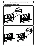
Page 25: ...LLATION Check the appliance is electrically safe and gas sound when you have finished 21 To Fit and Remove the Oven Shelf To remove the oven shelf To fit the oven shelf DocAUS 020 0004 Overview 110DF...

Page 26: ...ne gas is supplied with the range If the appliance is to be converted this must be done before installation The conversion must be performed by a qualified LP gas installer After conversion the instal...

Page 27: ...t Remove the orifice from its holder and replace with the griddle orifice for LPG 122 Ovens Remove the 4 fixing screws on the toe kick panel Hold the bottom edge lift up slightly and gently pull towar...

Page 28: ...ust be between 10 and 13 of water column 2 49 3 24 kPa When checking for proper operation of the regulator the inlet pressure must be at least 1 0 25 kPa greater than the operating manifold pressure a...

Page 29: ...2 55 18 47 19 54 74 73 58 17 Fan switch Light switch 18 light switch Right front Right rear Left front Left rear Oven thermostat 18 oven thermostat Broil safety valve 18 bake safety valve Griddle safe...

Page 30: ...26 Notes...

Page 31: ...27 Notes...

Page 32: ...www aga ranges com AGA Marvel 1260 E VanDeinse St Greenville MI 48838 Business 616 754 5601 Fax 616 754 9690 Toll Free Telephone 800 223 3900...

Reviews: