background image

32

ADJUSTING THE LCD DISPLAY

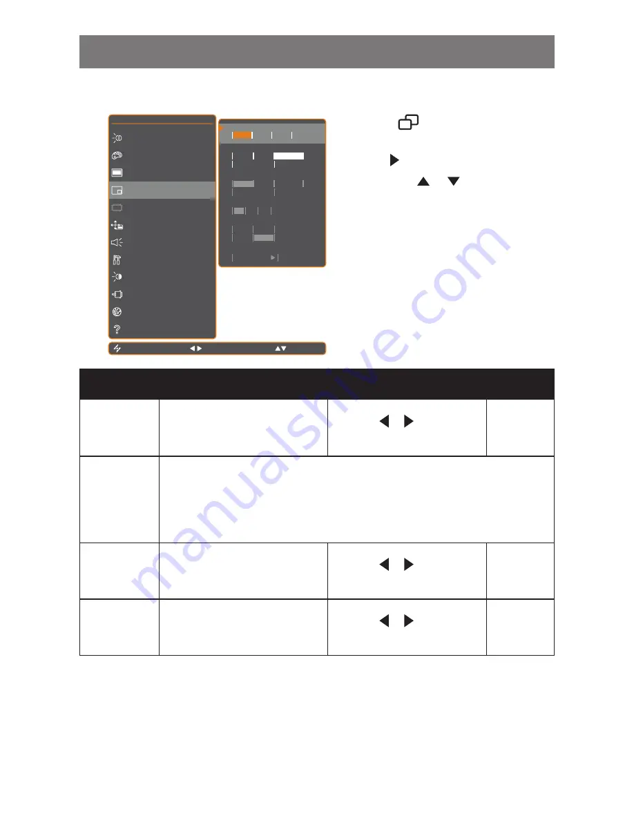
5.5 PIP Setting

E X I T

A D J U S T

S E L E C T

P I P

O F F

P I P

P A P

M A I N   S O U R C E

V G A

D V I

C V B S

S - V I D E O

S U B   S O U R C E

V G A

D V I

C V B S

S - V I D E O

S W A P

P R E S S

B R I G H T N E S S

C O L O U R   S E T T I N G

I M A G E   S E T T I N G

P I P   S E T T I N G

A N T I - B U R N - I N

O S D   S E T T I N G

A U D I O   S E T T I N G

O T H E R   S E T T I N G

A U T O   B R I G H T N E S S

I N P U T   S E L E C T

L A N G U A G E

I N F O R M A T I O N

S U B   P I C .   S I Z E

1

2

3

S U B   P I C .   P O S .

L + U

R + U

L + D

R + D

1 2 8 0 x 1 0 2 4   7 5 H z

1. Touch 

 to call out the OSD window.

2.  Select PIP SETTING menu, then touch 

the    button. 

3.  Touch the 

 or  

 buttons to select an 

option.

Item

Function

Operation

Range / 

Value

PIP

Allows you to select the PIP setting 
or disable PIP.

Touch the    or   buttons to 
select the value.

Off

PIP

PAP

PIP can be set to:

Off 

• 

- Disables PIP.

PIP

• 

 - The sub source image is within the main source image.

PAP

• 

 - The main source and sub source images are displayed side by side.

Main Source

Allows you to select the main source 
signal.

Touch the    or   buttons to 
select the value.

VGA / DVI 
/ CVBS / 
S-VIDE0

Sub Source

Allows you to select the sub source 
signal.

Touch the    or   buttons to 
select the value.

VGA / DVI 
/ CVBS / 
S-VIDE0

Summary of Contents for X-17P

Page 1: ...User Manual X 17P LCD Display ...

Page 2: ... Connections 13 2 1 Connecting the Power 13 2 2 Connecting Input Source Signals 14 2 2 1 Connecting a Computer 14 Using VGA Cables 14 Using DVI Cables 14 Connecting an Audio Device 15 2 2 2 Connecting a Camera or Video Device 15 Using CVBS Cables 15 Using S Video Cables 16 Chapter 3 Using the LCD Display 17 3 1 Turning on the Power 17 3 2 Selecting the Input Source Signal 17 3 3 Adjusting the Volu...

Page 3: ...Video signals 30 5 5 PIP Setting 32 5 6 OSD Setting 34 5 7 Audio Setting 35 5 8 Other Setting 36 5 9 Auto Brightness 38 5 9 1 EcoSmart Sensor 38 5 10 Input Select 39 Chapter 6 Appendix 40 6 1 Warning Messages 40 6 2 Troubleshooting 41 6 3 Transporting the LCD Display 42 Chapter 7 Specifications 43 7 1 Display Specifications 43 7 2 Display Dimensions 44 ...

Page 4: ...is device will produce use and emit radio frequency energy therefore installation or use without following the instructions given may cause damaging interference to radio communication Nonetheless it is not possible to state with certainty that interference will occur from specific installations If this device has caused damaging interference to radio or TV signals simply turn the device on and of...

Page 5: ...tronic equipment recycling For information about your recycling drop off area please contact your local related electrical and electronic equipment waste management authority or the retailer where you bought the product Hg Lamp Disposal LAMP S inside this product contain mercury and must be recycled or disposed of according to local state or federal laws For more information contact the electronic...

Page 6: ...ster online go to http www agneovo com To protect your rights as a consumer do not remove any stickers from the LCD display Doing so may affect the determination of the warranty period Cautions When Setting Up Do not place the LCD display near heat sources such as a heater exhaust vent or in direct sunlight Do not cover or block the ventilation holes in the housing Place the LCD display on a stabl...

Page 7: ...s surface and the housing Do not rub or tap the surface of the glass with sharp or abrasive items such as a pen or screwdriver This may result in scratching the surface of the glass Do not attempt to service the LCD display yourself refer to qualified service personnel Opening or removing the covers may expose you to dangerous voltage or other risks Warning Unplug the power cord from the power out...

Page 8: ...ystem is not in use Things to do when the LCD display shows image retention Turn off the LCD display for extended periods of time It can be several hours or several days Use a screen saver and run it for extended periods of time Use a black and white image and run it for extended periods of time When the LCD display is moved from one room to another or there is a sudden change from low to high amb...

Page 9: ...wing items are included in the package If any of them is missing or damaged contact your dealer User manual Power cord Note The pictures are for reference only Actual items may vary upon shipment Power adapter VGA cable Warranty card LCD Display Audio cable Chapter 1 Product Description ...

Page 10: ... 2 Remove the six screws securing the base stand from the LCD display 3 Detach the base stand 100mm 75mm 100mm 75mm Note Take measures to prevent the LCD display from falling down and lessen possible injury and damage to the display in case of earthquakes or other disasters Use only the 75 x 75 mm and 100 x 100 mm wall mount kit recommended by AG Neovo Secure the LCD display on a solid wall strong...

Page 11: ...swap the PIP main and sub picture When PIP is off press to rotate the image 180 During OSD menu selection press to move up a menu or submenu LEFT Press to decrease the volume During OSD menu selection press to adjust the settings RIGHT Press to increase the volume During OSD menu selection press to select an option and adjust the settings AUTO For VGA input signal source press to perform auto adju...

Page 12: ...g a VGA cable for analogue input signal S Video connector Use to connect AV cables for the S Video signal Audio port Use to connect an audio cable for the PC s audio input DVI connector Use to connect a PC using DVI cable for digital input signal 1 4 3 2 5 7 6 COMPOSITE Audio input connectors Use to connect RCA cables for CVBS S Video audio signal AUDIO IN DVI D SUB DC IN S VIDEO L R RCA Video 1 2...

Page 13: ...Connect the power cord plug to a power outlet or a power supply DC IN Caution Make sure that the LCD display is not connected to the power outlet before making any connections Connecting cables while the power is ON may cause electric shock or personal injury Caution When unplugging the power cord hold the power cord by the plug head Never pull by the cord Chapter 2 Making Connections ...

Page 14: ...VGA Cables Connect one end of a D sub cable to the VGA connector of the LCD display and the other end to the D sub connector of the computer D SUB Using DVI Cables Connect one end of a DVI cable to the DVI connector of the LCD display and the other end to the DVI connector of the computer DVI ...

Page 15: ...rt of the computer AUDIO IN 2 2 2 Connecting a Camera or Video Device L R RCA Video or Using CVBS Cables Connect one end of a CVBS cable to the COMPOSITE connector of the LCD display and the other end to the COMPOSITE connector of your device For audio input connect the RCA cables to the audio in connectors of the LCD display and the audio out connectors of your device ...

Page 16: ...nect one end of an S Video cable to the S VIDEO connector of the LCD display and the other end to the S VIDEO connector of your device For audio input connect an RCA cable to the audio in connector of the LCD display and the audio out connector of your device ...

Page 17: ...ompletely cut off power 3 2 Selecting the Input Source Signal SOURCE button Notes After selecting an input source signal the input source signal message appears on the screen briefly For example CVBS is selected the following message is displayed C V B S I N P U T If the selected input source signal is not connected to the LCD display or is turned off the no signal message is displayed on the scre...

Page 18: ... keypad To lock the OSD press and hold the keypad buttons listed below for at least 5 seconds or until the O S D L O C K O U T message appears When the OSD is locked all keypad buttons are inactivated Type of OSD Lock Lock Operation Unlock Operation Lock all buttons Touch and hold the and the buttons for 5 seconds Touch and hold the and the buttons for 5 seconds or until the OSD menu appears Lock ...

Page 19: ...d scroll among the PIP options Options are as follows Info PIP On The sub source signal is displayed within the main source signal PAP Picture and Picture The main source and the sub source signals are displayed side by side with equal display size PIP Off PIP function is disabled only the main source signal is displayed Note The main source and sub source signals can be set in PIP Settings see pa...

Page 20: ... Main source Sub source 3 6 Using ROTATE Function The ROTATE function allows you to rotate the screen image at 180 Original screen image Touch the button to rotate the picture 180º See illustration below After ROTATE image Note ROTATE function can only be executed if PIP is off see page 32 After executing ROTATE touch the button again to rotate the picture back to its normal state Note PIP Swap ca...

Page 21: ...uto adjustment The message auto adjusting is displayed on the screen A U T O A D J U S T I N G During auto adjustment the screen will slightly shake for a few seconds When the message disappears auto adjustment is completed Note Auto Adjustment function is available only during VGA input signals It is recommended to use the auto adjustment function when using the LCD display for the first time or ...

Page 22: ...O B R I G H T N E S S I N P U T S E L E C T L A N G U A G E I N F O R M A T I O N Touch 2 Select the menu E X I T E N T E R S E L E C T 1 2 8 0 x 1 0 2 4 7 5 H z B R I G H T N E S S 5 0 C O N T R A S T 5 0 B L A C K L E V E L 5 0 B R I G H T N E S S C O L O U R S E T T I N G I M A G E S E T T I N G P I P S E T T I N G A N T I B U R N I N O S D S E T T I N G A U D I O S E T T I N G O T H E R S E T ...

Page 23: ...T I N G U D I O S E T T I N G T H E R S E T T I N G U T O B R I G H T N E S S N P U T S E L E C T A N G U A G E N F O R M A T I O N 8 0 x 1 0 2 4 7 5 H z B L A C K L E V E L 5 0 The highlighted item with an orange arrow indicates the active submenu Touch the or buttons 4 Adjust the settings Touch the or buttons 5 Exit the submenu Touch or to return to the previous menu 6 Close the OSD window Touch...

Page 24: ...Sharpness Phase Clock H Position V Position See page 29 E X I T E N T E R S E L E C T 1 2 8 0 x 1 0 2 4 7 5 H z B R I G H T N E S S 5 0 C O N T R A S T 5 0 B L A C K L E V E L 5 0 B R I G H T N E S S C O L O U R S E T T I N G I M A G E S E T T I N G P I P S E T T I N G A N T I B U R N I N O S D S E T T I N G A U D I O S E T T I N G O T H E R S E T T I N G A U T O B R I G H T N E S S I N P U T S E ...

Page 25: ...Position See page 30 4 PIP Setting PIP Main Source Sub Source Sub Picture Size Sub Pic Pos Swap See page 32 5 OSD Setting Transparency H Position V Position OSD Timer See page 34 6 Audio Setting Volume Audio DVI Source See page 35 7 Other Setting Power Saving Mode DDC CI DCR Recall See page 36 8 Auto Brightness Enable Mode Level See page 38 9 Input Select VGA DVI CVBS S Video See page 39 ...

Page 26: ...in Menu Submenu Remarks 10 Language Select the OSD language EN FR DE ES IT PY RO PL CS NL TC SC 11 Information Displays settings information such as Input Resolution Horizontal and Vertical Frequency Time mode and Firmware version ...

Page 27: ...A T I O N 1 2 8 0 x 1 0 2 4 7 5 H z B L A C K L E V E L 5 0 1 Touch to call out the OSD window 2 Select BRIGHTNESS menu then touch the button 3 Touch the or buttons to select an option Item Function Operation Range Brightness Adjusts the luminance of the screen image Note Brightness setting is disabled if Auto Brightness is On Touch the or buttons to adjust the value 0 to 100 Contrast Adjusts the ...

Page 28: ...400K 9300K sRGB USER Colour temperature can be set to 6500K This is the default colour temperature commonly used for normal lighting conditions 5400K Applies a reddish tint for warmer colours 9300K Applies a bluish tint for cooler colours sRGB This is the Red Green Blue RGB colour standard which is used for colour management in most industries This setting displays accurate colours and suitable fo...

Page 29: ...0 H P O S I T I O N 5 0 V P O S I T I O N 5 0 E X I T A D J U S T S E L E C T 1 2 8 0 x 1 0 2 4 7 5 H z 1 Touch to call out the OSD window 2 Select IMAGE SETTING menu then touch the button 3 Touch the or buttons to select an option Item Function Operation Range Sharpness Adjusts the clarity and focus of the screen image Touch the or buttons to adjust the value 0 to 100 Phase Adjusts the phase timi...

Page 30: ... T N E S S I N P U T S E L E C T L A N G U A G E I N F O R M A T I O N 1 2 8 0 x 1 0 2 4 7 5 H z 1 Touch to call out the OSD window 2 Select IMAGE SETTING menu then touch the button 3 Touch the or buttons to select an option Item Function Operation Range Value Sharpness Adjusts the clarity and focus of the screen image Touch the or buttons to adjust or select the value 0 to 100 Saturation Adjusts ...

Page 31: ...OVERSCAN The aspect ratio increases by 5 UNDERSCAN The aspect ratio decreases by 5 NATIVE The aspect ratio returns to its default size H Zoom Horizontal Zoom Adjusts the horizontal zoom Touch the or buttons to adjust the value 0 to 100 V Zoom Vertical Zoom Adjusts the vertical zoom H Position Horizontal Position Moves the screen image to the left or right V Position Vertical Position Moves the scr...

Page 32: ... P I C P O S L U R U L D R D 1 2 8 0 x 1 0 2 4 7 5 H z 1 Touch to call out the OSD window 2 Select PIP SETTING menu then touch the button 3 Touch the or buttons to select an option Item Function Operation Range Value PIP Allows you to select the PIP setting or disable PIP Touch the or buttons to select the value Off PIP PAP PIP can be set to Off Disables PIP PIP The sub source image is within the ...

Page 33: ...rner of the screen R U Sets the image on the upper right corner of the screen L D Sets the image on the lower left corner of the screen R D Sets the image on the lower right corner of the screen Swap Swaps the main source and sub source signals Touch the button to swap the image sources Main Sub VGA DVI CVBS S VIDEO VGA not supported not supported Y Y DVI not supported not supported Y Y CVBS Y Y n...

Page 34: ... F O R M A T I O N 1 2 8 0 x 1 0 2 4 7 5 H z 1 Touch to call out the OSD window 2 Select OSD SETTING menu then touch the button 3 Touch the or buttons to select an option Item Function Operation Range Transparency Adjusts the transparency level of the OSD screen Touch the or buttons to adjust the value 0 to 100 H Position Horizontal Position Moves the OSD window to the left or right of the screen ...

Page 35: ...Touch the or buttons to select an option Item Function Operation Range Value Volume Adjusts the volume level of the built in speaker Touch the or buttons to adjust the value 0 to 100 Audio Turns the audio speaker ON or OFF Note Even when Audio is set to Off Audio is automatically turned on when volume is adjusted Touch the or buttons to select the value On Off DVI Source Available only during DVI ...

Page 36: ...wer Saving Enables or disables power saving mode When the LCD display turns into power saving mode the screen turns black and the LED indicator lights AMBER Touch the or buttons to select the value On Off Mode Sets the current mode for better image display Touch the or buttons to select the value Text Graphic Available only during computer input signal when the resolution is either of the followin...

Page 37: ...provides automatic adjustment of picture brightness and contrast at high speed and dynamic contrast range such as when watching movies DCR is suitable for indoor viewing Touch the or buttons to select the value On Off Recall Use to recall all to default settings except Language PIP and the input source Touch the button ...

Page 38: ...N E X I T A D J U S T S E L E C T M O D E U S E R E N A B L E O N O F F L E V E L A U T O 8 0 1 2 8 0 x 1 0 2 4 7 5 H z 1 Touch to call out the OSD window 2 Select AUTO BRIGHTNESS menu then touch the button 3 Touch the or buttons to select an option Item Function Operation Value Enable Enables or disables auto brightness Touch the or buttons to select the value On Off Mode Sets the auto brightness...

Page 39: ...I N G O T H E R S E T T I N G A U T O B R I G H T N E S S I N P U T S E L E C T L A N G U A G E I N F O R M A T I O N 1 2 8 0 x 1 0 2 4 7 5 H z 1 Touch to call out the OSD window 2 Select INPUT SELECT menu then touch the button 3 Touch the or buttons to select an option Item Function Operation Value VGA Sets VGA as the input source signal Touch the button to select DVI Sets DVI as the input source...

Page 40: ...oo high Change the resolution or the refresh rate of the graphics card N O S I G N A L The LCD display cannot detect the input source signal Check if the input source is turned ON Check if the signal cable is properly connected Check if any pin inside the cable connector is twisted or broken O S D L O C K O U T The OSD has been locked by the user Unlock the OSD Refer to page 18 Chapter 6 Appendix ...

Page 41: ...ue green white dots appear on screen There are millions of micro transistors inside the LCD display It is normal for a few transistors to be damaged and to produce spots This is acceptable and is not considered a failure No audio output Check if the volume is set to 0 see page 18 or 35 Check if AUDIO is set to OFF see page 35 For VGA or DVI input check the audio setting of the computer Dew formed ...

Page 42: ...for repair or shipment place the display in its original packaging carton 1 Place the two foam cushions on each side of the LCD display for protection 2 Place the LCD display down in the box 4 Put all other contents on the designated area if necessary 5 Close and tape the box ...

Page 43: ... Video Input VGA 15 Pin Mini D Sub DVI D 24 Pin DVI D CVBS RCA x 1 S Video 4 Pin mini DIN Audio Audio In 1 x stereo audio in for PC 1 x stereo audio in for CVBS RCA and S Video Speaker 1 5W x 2 Operating Conditions Temperature 0 C 40 C 32 F 104 F Humidity 10 90 Storage Conditions Temperature 20 C 60 C 4 F 140 F Humidity 5 95 Weight Without Base 5 8 kg 12 8 lbs With Base 6 6 kg 14 5 lbs Note All sp...

Page 44: ...44 SPECIFICATIONS 7 2 Display Dimensions 361 7mm 278mm 240mm 172mm 409 2mm 69 5mm 100mm 37mm 75mm 100mm 75mm ...

Reviews: