background image


Confirming the Installation Environment and Location to Install the Machine 

- 13 - 


Confirming the Installation Environment and 
Location to Install the Machine 

For safe and comfortable operations, install the 
product in a location that satisfies the conditions 
in 

Precautions related to installation

Installation Environment

, and 

Installation 

Space 

as described below. This section also has 

precautions related to installation. Be sure to 
read these before starting installation work. 


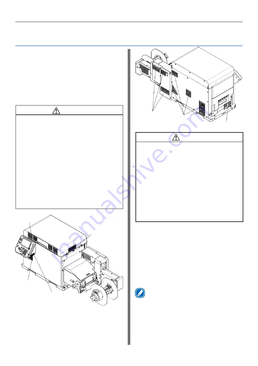
Precautions related to installation 


Left side of printer 


CAUTION 


Do not install the equipment on a thick-piled carpet 

or rug. 


Do not install the equipment in a location that is 

poorly ventilated or stuffy. 


Pay attention to ventilation when operating the 

equipment continuously for a long period in a small 

room. 


Install the equipment away from sources of strong 

magnetic or electric noise. 


Install the equipment away from monitors or 

televisions. 


Remember to use ventilation when printing large 

volumes or operating the equipment continuously 

for a long period. 


The machine’s acoustic power level exceeds 6.3B, 

so recommend that it be installed in a room 

separate from office work areas. 

Consider the following environment conditions 

when you select the installation location. 

[Installation Environment] 
Use a location that is within the following ranges 
for temperature and humidity. 


Temperature range: 

10 to 30

º

C (50-85

 º

F) 

Humidity range: 

30 to 70% RH 
(relative humidity) 

Maximum wet-bulb 

temperature: 

25

º

C (77

 º

F) 


Memo


Be careful that condensation does not form. 


If you install the equipment in a location where the 

humidity is in a range of less than 30%, use a humidifier 

or anti-static mat. 

Front of printer's 
top cover 

Right side of 
printer's  top 
cover 

Front of printer 


Control panel 

Back of unwinder 

Back of printer 

  WARNING 


Do not install the equipment in a location that is 

near open flame or may become very hot. 


Do not install the equipment in a location prone to 

chemical reactions (laboratory, etc.). 


Do not install the equipment in a location that is 

near flammable liquids, such as alcohol or paint 

thinner. 


Do not install the equipment in a location that is 

accessible by small children. 


Do not install the equipment in a location that is 

unstable (on a wobbly table or inclined place). 


Do not install the equipment in direct sunlight or in 

a very dusty or humid location. 


Do not install the equipment in an environment 

subject to salt air, NOx, SOx or corrosive gases. 


Do not install the equipment in a location that is 

subject to excessive vibration. 


Do not install the equipment in a location where 

the machine's vents are blocked. Check the 

positions of the vents in the following illustration. 


Summary of Contents for LT5C

Page 1: ...LT5C Label Printer Installation Guide v1 0...

Page 2: ...stallers and users Setup Guide This manual describes how to connect the printer to a computer and set it up following installation User s Guide This manual describes details about product functions an...

Page 3: ...es not need to replace the lithium batteries inside the equipment during the service life of the equipment However when disposing of a lithium battery for whatever reason insulate the positive and neg...

Page 4: ...s 9 2 Installation 11 Checking the Product 11 Printer 11 Unwinder 12 Confirming the Installation Environment and Location to Install the Machine 13 Unpacking 16 Printer 16 Unwinder 20 Unwinder Configu...

Page 5: ...achine Users and Machine Installers Product name Label Printer LT5C Before starting work carefully read Label Printer LT5C Label Printer Residual Risk provided as a separate document with the product...

Page 6: ...re or injury may result Unplug the power plug regularly and clean the bases of and in between the plug blades If the power plug is left plugged into the outlet for an extended period of time dust adhe...

Page 7: ...es does not necessarily constitute endorsement by the manufacturer While all reasonable efforts have been made to make this document as accurate and helpful as possible we make no warranty of any kind...

Page 8: ...8 Overview of Configuration The equipment is configured of the following units Label Printer LT5C Printer Unwinder Equipment configuration Printer 1 Before Installation Unwinder...

Page 9: ...units for the equipment Inside printer Print cartridge 1 Printer Top cover Interface Paper ejection slot Fuser and exit unit LED heads Belt unit including waste toner box Power connector Control panel...

Page 10: ...lected items and set values 5 HELP Displays the help screen 6 BACK Returns to the previous screen 7 ATTENTION lamp Displays the state of the machine Turns off when normal Lights or flashes orange when...

Page 11: ...t 43 kg 95 lb and requires at least two people to lift it Including the print cartridge and other consumables Printer Printer Print cartridges One each of yellow magenta cyan black and white Installer...

Page 12: ...Checking the Product 12 Unwinder Unwinder Mounting screws 3 Cable clamps 3...

Page 13: ...nstallation location Installation Environment Use a location that is within the following ranges for temperature and humidity Temperature range 10 to 30 C 50 85 F Humidity range 30 to 70 RH relative h...

Page 14: ...Confirming the Installation Environment and Location to Install the Machine 14 External Dimensions 477 mm 18 75 in 1040 mm 41 in 441 mm 17 35 in...

Page 15: ...e on all four sides and above for access For safety the unwinder should not hang over the edge of any support To install the printer and the unwinder on a stand or table it must be at least 1050 mm 42...

Page 16: ...use the control panel may come off and you could drop the equipment Place the equipment on the floor to remove the packing materials and the plastic bag There is a risk of dropping the equipment and c...

Page 17: ...es and then remove the top of the packing box Open out the bottom part of the box place your hands on the printer s handles 2 in front 2 in back and support the printer as you remove the front and bac...

Page 18: ...tallation space that you have prepared in advance see page 15 6 Remove the plastic bag Note Allow enough space to work when installing the unwinder The weight of the equipment including consumables is...

Page 19: ...g tape 4 pieces from the edges of the top cover Holding tape Remove the Pad TC from the top of the print cartridge and then remove the tape that is securing the lift levers The print cartridges lift u...

Page 20: ...ow them away 14Close the top cover Note When closing the top cover there is a risk of pinching your fingers or hands in the top cover or the top cover s support Press on the top of the top cover to cl...

Page 21: ...ng 21 5 Peel off the tape from two locations Remove the plastic bag from the unwinder and then remove the accessories Refer to the following pages regarding installation to the printer Remove the unwi...

Page 22: ...e the following procedure to change the unwinder s settings Remove screw from the unwinder and then remove the switch cover 2 Raise switch 1 to the left side of DIP SW Installing Cable Clamps Cable cl...

Page 23: ...here is a risk that the unwinder may fall off or the print quality may be degraded Check whether the adjuster on the unwinder is raised up If the adjuster is not raised before you mount it on the prin...

Page 24: ...e unwinder to the printer Tighten the screws in order 1 2 then 3 as shown in the following diagram Extend the adjuster so it contacts the stand Note Be careful not to extend the adjuster too far The u...

Page 25: ...here is a risk of fire Be sure to turn off the power switch before attaching or removing the power cord or ground wire Leaving the power turned on could result in a fire or electric shock Be sure to c...

Page 26: ...power plug into the power socket Press and hold the POWER button for approximately 1 second When the power is turned on the LED lamp on the POWER button turns on Memo When the machine starts the Afini...

Page 27: ...the machine s power automatically turns off and the LED lamp on the POWER button turns off Memo Pressing on the POWER button for five seconds or longer forces the power to turn off Do this only if so...

Page 28: ...imes to select Adjust Density and then press the OK button Check that Execute has been selected and press the OK button Press the scroll button several times and when Print Information appears press t...

Page 29: ...inder s black mark gap sensors and the printer according to the media you are using Refer to the User s Guide regarding how to adjust the positions of the sensors Printer Black mark Gap sensor Unwinde...

Page 30: ...Afinia Label 8150 Mallory Court Chanhassen MN 55317 https www afinialabel com Dec 2019...

Reviews: