background image

Tel. +39 049 641 679 

|

 [email protected] 

|

 www.aercomponents.it

31

EN

11. MAINTENANCE

–  TURN OFF all the power switches before the maintenance is performed.

–  Do not operate the system without the air filter to protect the components of the unit against 

being clogged.

–  Clean up the air filter every 3 months. Filters should be replaced every 6 months.

–  Clean up the heat exchanger every 2 years.

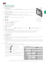
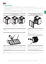
Air Filter Cleaning

Heat Exchanger Cleaning

Pulizia Scambiatore

Pulizia Filtro dell'Aria

Scorrere verso 


i filtri

Slide the service 

cover left

Open the service 

cover left

Remove 

the filters

Pulizia Scambiatore

Pulizia Filtro dell'Aria

Scorrere verso 


i filtri

Step 1 - 

Slide left, open the service cover and then remove 

the filters.

Step 1

 - Remove the front cover plate, 

then remove the heat exchanger out 

from the main unit.

Vacuum cleaner Filter

NOTE

 - The maximum weight of heat 

exchanger is 5.5 kg.

Heat exchanger

Vacuum cleaner

Step 2

 - Use a vacuum cleaner to suck up the dust from the 

air filter. If necessary, use warm water with addition a house 

detergent to remove the persistent dirt. Leave to dry after 

cleaning the air filter.

Step 2

  -  No  cleaning  with  fluids 

(including water); only careful dust 

removal from air intake su faces with a 

household vacuum cleaner.

NOTE

 - If F class filter is used, when filter gets dirty, do not clean! F class filters must be replaced if it is dirty

Summary of Contents for RECAR227

Page 1: ...MANUALE DI INSTALLAZIONE E D USO INSTALLATION AND USE MANUAL RECAR227 ...

Page 2: ... persona autorizzata a costituire il Fascicolo Tecnico è il Rappresentante Legale Sig Gennaro Scognamiglio reperibile in AERSERVICE COMPONENTS con sede all indirizzo sotto indicato Conforme con Direttiva macchine 2006 42 CE Direttiva bassa tensione 2014 35 UE Direttiva EMC 2014 30 UE DICHIARAZIONE DI INCORPORAZIONE Allegato 2 paragrafo B 2006 42 CE La AERSERVICE COMPONENTS S r l dichiara inoltre c...

Page 3: ...ZIONI DI SICUREZZA pag 4 1 COMPONENTI 5 2 SMALTIMENTO 5 3 DATI TECNICI 7 4 CURVA PRESTAZIONALE 8 5 DIMENSIONI DELL UNITÀ 9 6 SPAZI0 DI FUNZIONAMENTO 9 7 INSTALLAZIONE 10 8 SCHEMA ELETTRICO 12 9 TIPOLOGIA DI SEZIONE TRASVERSALE DEL CAVO ELETTRICO 13 10 SISTEMA DI CONTROLLO 14 11 MANUTENZIONE 16 IT ...

Page 4: ...tazione adeguatamente sicura e installare il prodotto correttamente e saldamente Collegare saldamente i cavi elettrici forniti in dotazione alla morsettiera in modo tale che non possano essere scollegati Collegamenti scorretti potrebbero provocare incendi Gli eventuali canali metallici passanti all interno di edifici in legno rivestiti di listelli metallici griglie o metallo devono essere installa...

Page 5: ...in base al materiale di costruzione lamiere in acciaio zincato e o preverniciato poliuretano espanso polipropilene espanso lana minerale materiale elettrico e o elettronico Devono essere adottati tutti gli accorgimenti necessari atti ad evitare danni a persone e cose e l inquinamento dell ambiente circostante Per maggiori informazioni contattare l installatore o le autorità locali Direttiva RAEE s...

Page 6: ...pporto con la AERSERVICE COMPONENTS S r l citare sempre tipo e o numero di serie indicati su questa targa IDENTIFICAZIONE DELLA MACCHINA Ogni unità è provvista di una targhetta identificativa che contiene i principali dati della macchina A I R E N G I N E E R I N G www it UNITÀ TIPO UNIT TYPE NUMERO SERIE SERIES NUMBER CODICE VENTILATORE FAN CODE POTENZA INSTALLATA POWER IN PUT Kw CORRENTE ASSORBI...

Page 7: ...erimento Lwa 57 4 Portata di riferimento m s 0 044 Differenza di pressione di riferimento Pa 50 SPI Potenza Assorbita Specifica W m h 0 289 Fattore di controllo e tipologia 1 Manuale Percentuale di trafilamento dichiarato 0 8 Interno 0 5 Esterno Percentuale di miscela 0 Posizione e descrizione delle avvertenze relative ai filtri www aercomponents it Istruzioni relative alle griglie www aercomponen...

Page 8: ...seguito a 1 5 metri di distanza dall unità RECA227 IT 350 300 250 150 200 100 50 0 50 100 150 200 250 300 Quantità volumetrica d aria m3 h Pressione statica esterna Pa 70 dB 60 50 40 30 20 10 63 125 250 500 1000 2000 4000 8000 Livello di pressione sonora in ottava dB scala A complessiva Frequenza centrale ciclo al secondo Hz ...

Page 9: ...60 702 125 Vista superiore IT RECA227 Ø125 600 380 660 400 702 Vista frontale Mandata Ripresa Vista superiore Il peso dell unità è di 24 kg Tutti i valori di misura sono espressi in mm Espulsione Aria Esterna Distanza minima consigliata 400 mm Davanti all unità deve essere assicurato uno spazio libero di 400 mm per permettere il corretto funzionamento È necessario installare una tubazione di scari...

Page 10: ...A Tra il lato inferiore dell unità e il pavimento deve essere assicurata una distanza minima di 80 mm per permettere un agevole installazione della tubazione di scarico 600 500 min 110 mm 600 500 min 110 mm 7 INSTALLAZIONE INSTALLAZIONE A MURO 1 Avvitare le due staffe da parete sul lato posteriore dell unità utilizzando gli idonei accessori 4 pz M5x10 2 Fissare le due staffe alla parete le distanz...

Page 11: ...raccordo della tubazione di scarico deve avere un diametro di almeno 20 mm e un adeguata pendenza la tubazione di scarico non può essere collegata direttamente per nessuna ragione INSTALLAZIONE Codifica Sn Ds EA OA SA RA Si può notare un raccordo sulla parte superiore 1 0 Si può notare un raccordo sulla parte superiore 1 0 Si può notare un raccordo sulla parte superiore 1 0 Si può notare un raccord...

Page 12: ...e aercomponents it www aercomponents it 12 8 SCHEMA ELETTRICO IT BYPASS Collegamento alla rete Sensore di temperatura Estrazione Sensore di temperatura Esterna Ventilatore di Espulsione Ventilatore di Mandata Pannello di controllo ...

Page 13: ... DI RECUPERO CALORE 230V MONOFASE Modello Unità Diametro del riscaldatore mm Unità di potenza in ingresso W Fusibile A Sezione trasversale cavo mm 1 5 2 5 4 6 10 16 RECAR227 125 0 5 6 122 203 1 6 61 102 163 1 5 10 41 68 109 163 NOTA I valori riportati in tabella si riferiscono alla lunghezza del cavo in metri m Proprietà cavo 3 x fase neutro terra CAPACITÀ ELETTRICA DEL RISCALDATORE DEL RECUPERATO...

Page 14: ...e elettriche Azionare il dispositivo tra 0 C e 40 C Per la pulizia del dispositivo utilizzare esclusivamente un panno morbido e umido Evitare l uso di prodotti abrasivi o detergenti chimici Non verniciare il dispositivo 3 DESCRIZIONE 3 1 Destinazione d uso Il dispositivo è concepito per impostare il livello di ventilazione attraverso la velocità della ventola impostata dall utente Ogni diverso o u...

Page 15: ...remere una volta per una durata di 30 minuti premere due volte per una durata di 60 minuti premere tre volte per una durata di 90 minuti Il dispositivo mostrerà il risultato sul LED di stato 6 RESET ALLARME FILTRI SPORCHI Per resettare il messaggio di filtri sporchi premere contemporaneamente i tasti away e party ed attendere almeno 4 secondi 7 SOSTITUZIONE DELLE BATTERIE Vedere paragrafo 4 per ma...

Page 16: ...pezione Rimuovere i filtri Pulizia Scambiatore Pulizia Filtro dell Aria Scorrere verso i filtri Step 1 Aprire la porta di ispezione e rimuovere i filtri Step 1 Smontare il pannello frontale e rimuovere lo scambiatore di calore Aspirapolvere Filtro NOTA Il massimo peso dello scambiatore di calore è di 5 5 Kg Scambiatore di calore Aspirapolvere Step 2 Utilizzare un aspirapolvere per aspirare la polv...

Page 17: ...e Mr Scognamiglio Gennaro available in AERSERVICE COMPONENTS located at the address below In particular the analysis of the risk of the machine described complies with the harmonized UNI EN ISO 12100 2010 and the following harmonized standards Directive 2006 42 CE Directive 2014 35 UE Low Voltage Directive 2014 30 UE Electromagnetic Compatibility EMC DECLARATION OF INCORPORATION Annex 2 paragraph ...

Page 18: ... INDEX 0 WARNINGS SAFETY INFORMATION page 19 1 COMPONENTS 20 2 DISPOSAL 20 3 TECHNICAL DATA 22 4 PERFORMANCE CURVE 23 5 UNIT DIMENSIONS 24 6 SERVICE SPACE 24 7 INSTALLATION 25 8 WIRING DIAGRAM 27 9 SELECTION OF ELECTRICAL CABLE CROSS SECTION 28 10 CONTROL SYSTEM 29 11 MAINTENANCE 31 ...

Page 19: ...sition for installing the product and install it properly and securely Use the designated electrical wires for the terminal board connections and connect the wires securely so that they will not be disconnected Failure to ensure proper connections may result in fire When passing metal ducts through wooden buildings clad with metal laths wire laths or metal these ducts must be installed in such a w...

Page 20: ...ropriate specialized centers according to the construction material galvanized and or prepainted steel sheets polyurethane foam expanded polypropylene mineral wool electrical and or electronic equipment All necessary precautions must be taken to prevent damage to people and property and pollution of the surrounding environment For more information contact the installer or local authorities WEEE DI...

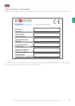
Page 21: ...any relationship with the AERSERVICE COMPONENTS S r l always quote the type and or serial number shown on this plate IDENTIFICATION OF THE MACHINE Each unit is equipped with a identification plate that contains important data on the machine A I R E N G I N E E R I N G www it UNITÀ TIPO UNIT TYPE NUMERO SERIE SERIES NUMBER CODICE VENTILATORE FAN CODE POTENZA INSTALLATA POWER IN PUT Kw CORRENTE ASSO...

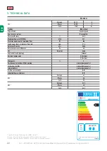
Page 22: ...ximum flow W 106 Sound power level at reference flow rate Lwa 57 4 Reference flow rate m s 0 044 Reference pressure difference Pa 50 SPI W m h 0 289 Control factor and typology 1 Manual Declared leakage rates 0 8 Internal 0 5 External Mixing rate 0 Position and description of filter warning www aercomponents it Instruction of grilles www aercomponents it Internet address www aercomponents it Air f...

Page 23: ...ustic test is performed 1 5 meter away from the unit RECA227 350 300 250 150 200 100 50 0 50 100 150 200 250 300 Volumetric air volume m3 h External static pressure Pa 70 dB 60 50 40 30 20 10 63 125 250 500 1000 2000 4000 8000 Octave sound pressure level dB overall A scale Central frequency Cycle per second Hz ...

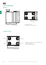
Page 24: ...a minima consigliata 400 mm 600 660 702 125 View from top RECA227 Ø125 600 380 660 400 702 View from front Supply Air Return Air View from top Unit weight is 24 kg All measurement values are mm Exhaust air Outdoor Air Recommended clear space 400 mm A clear space of 400 mm must be provided in front of the unit for service Drain pipe must be installed EN ...

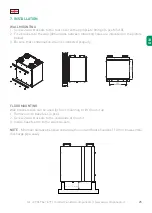
Page 25: ...eet on to the wall brackets NOTE Minimum distance between underside the unit and floor should be 110 mm to assemble discharge pipe easily 600 500 min 110 mm 600 500 min 110 mm 7 INSTALLATION WALL MOUNTING 1 Screw 2 wall brackets to the rear cover with appropriate fittings 4 pcs M5x10 2 Fit 2 brackets to the wall dimensions between mounting holes are indicated on the picture below 3 Be sure that co...

Page 26: ... to main drainage line should not be less than the diameter of the drainage outlet connection Not less then a diameter of 20 mm 2 A union or pipe coupling should be fitted at the pipe connections to permit easy disconnection to clean any dirt sediments 3 The connection drain pipe shall have a diameter of at least 20 mm and a sufficient slope under no circumstance may the drain pipe be connected di...

Page 27: ...l 39 049 641 679 commerciale aercomponents it www aercomponents it 27 EN 8 WIRING DIAGRAM BYPASS Grid conncetion Extract temperature sensor Outdoor temperature sensor Exhaust fan Supply fan Control panel ...

Page 28: ...h ELECTRICAL CABLE SELECTION OF ELECTRIC HEATER 230V 1 PHASE Unit Model Heater Diameter mm Unit Power Input KW Fuse A Cable Cross Section mm 1 5 2 5 4 6 10 16 RECAR227 125 0 5 6 122 203 1 6 61 102 163 1 5 10 41 68 109 163 NOTE The values given in the table is the length of the cable in meters m Cable property 3 x phase neutral earth ELECTRIC HEATER CAPACITY OF HEAT RECOVERY UNIT 230V 1 PHASE Unit ...

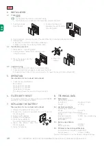
Page 29: ...use any abrasive or chemical cleaner Do not paint the device 3 DESCRIPTION 3 1 Intended use The device is designed for the purpose to set the level of ventilation through the fan speed based on user input Every other or further use is not in conformance with the intended use 3 2 Working principle The device communicates with the control device using wireless communications in order to control the ...

Page 30: ...ress 2x for 60 minutes press 3x for 90 minutes The device shows the result on the status LED 6 FILTER DIRTY RESET To reset the filter dirty message press and hold AWAY and PARTY for at least 4 seconds 7 REPLACING THE BATTERY See section 4 for more visual instructions 1 Remove the buttons from the unit 2 Loosen the clips and separate the unit from the mounting plate 3 Replacing the battery a Remove...

Page 31: ...s Pulizia Scambiatore Pulizia Filtro dell Aria Scorrere verso i filtri Step 1 Slide left open the service cover and then remove the filters Step 1 Remove the front cover plate then remove the heat exchanger out from the main unit Vacuum cleaner Filter NOTE The maximum weight of heat exchanger is 5 5 kg Heat exchanger Vacuum cleaner Step 2 Use a vacuum cleaner to suck up the dust from the air filte...

Page 32: ...AERSERVICE COMPONENTS Srl www aercomponents it Via Marconi 1 35020 Legnaro PD P IVA e CF 04888500289 Tel 39 049 641679 Fax 39 049 790674 commerciale aercomponents it ...

Reviews: