AerPOS Series AP-3615
9
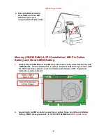
4. During the MB installation,
Please Make sure the MB
Golden finger is well
connected with IO Board Slot.
Memory (DDRIII RAM) & CPU Installation / MB Pin Define,
Battery and Clear CMOS Setting
1.
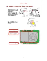
Disassembly the MB Module, then Memory installation can be done from the top side
of MB Module. CPU installation has to remove Thermal Fan Module by 2 screws, after
the CPU installation, please ensure the thermal pads between CPU, chipset and
heatsink are well contacted.
2.
According to the MB on-board connectors or golden finger pin define and Battery
Setting, CMOS Clear, please refer to the FH-H611 MB Manual.
(Will update soon)
DDR-3 204Pin
Memory Slot
Smart Fan Heatsink
CPU & Chipset
Summary of Contents for AP-3615
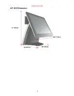
Page 8: ...AerPOS Series AP 3615 3 AP 3615 Dimension D 235mm W 240mm H 360mm W 370mm...
Page 27: ...AerPOS Series AP 3615 22 5 Finally Finish and Restart the system...
Page 29: ...AerPOS Series AP 3615 24 5 Finally Finish and Restart the system...
Page 31: ...AerPOS Series AP 3615 26 5 Finally Finish and Restart the system...
Page 36: ...AerPOS Series AP 3615 31...

