2.2.8. Auxiliary Encoder Input
The Axis connector gives you a second encoder input channel. This channel is typically used for dual
loop applications.
Use the AuxiliaryFeedbackType parameter to configure the drive to accept an encoder signal type.
Square Wave encoder signals:
You can configure the Auxiliary Encoder interface as an output that will transmit encoder signals for
external use. Use the DriveEncoderOutputConfigureInput() function to configure the Sine ± and
Cosine ± connector pins as RS-422 outputs. You can only echo incremental square wave primary
encoder inputs.
Table 2-20:
Auxiliary Encoder Pins on the Axis Connector
Pin #
Description
In/Out/Bi
5
Auxiliary Sine +
Bidirectional
6
Auxiliary
Bidirectional
18
Auxiliary Sine -
Bidirectional
19
Auxiliary Cosine -
Bidirectional
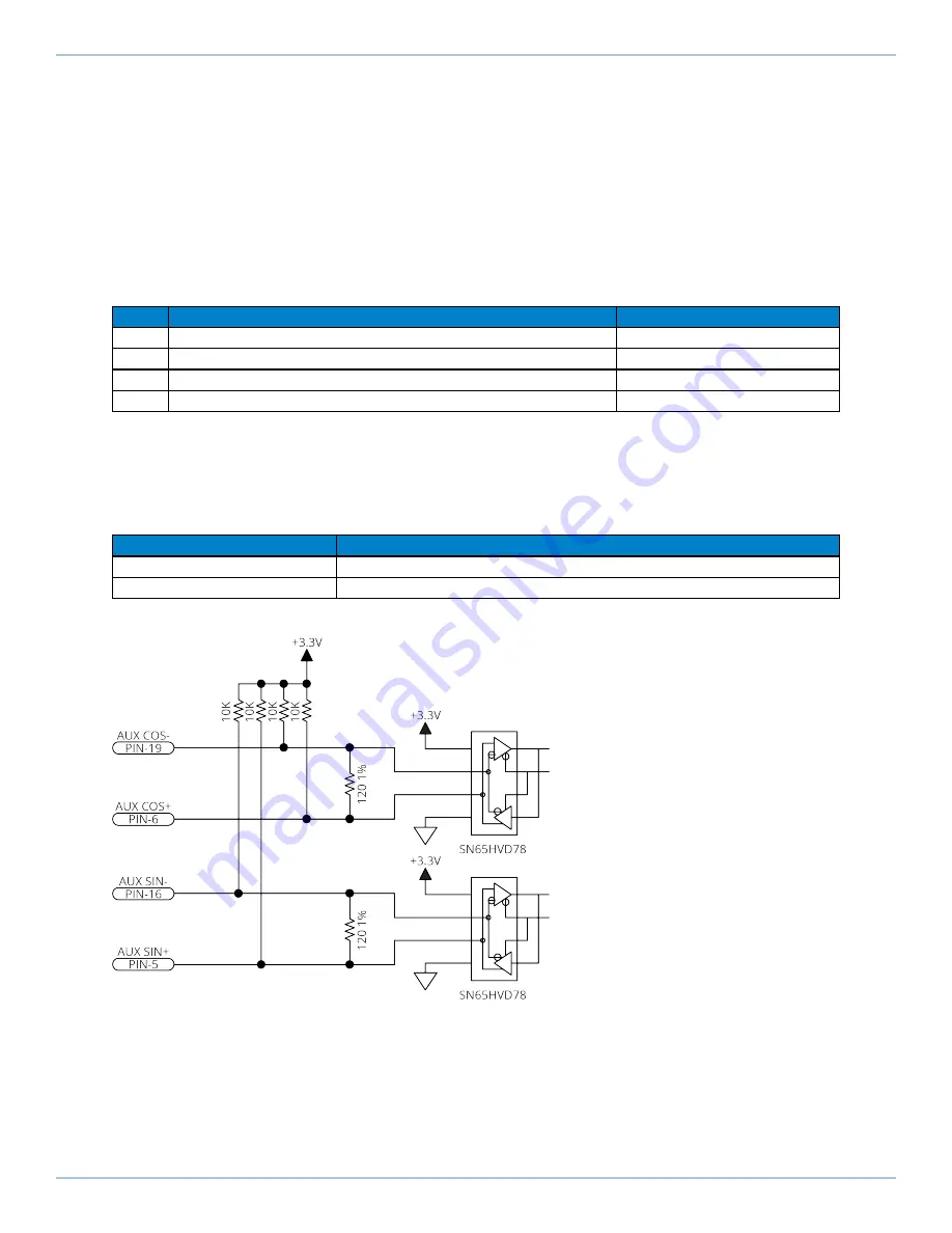
2.2.8.1. Square Wave Encoder (Auxiliary)
The drive accepts RS-422 square wave encoder signals. The drive will generate a feedback fault if it
detects an invalid signal state caused by an open or shorted signal connection. Use twisted-pair
wiring for the highest performance and noise immunity.
Table 2-21:
Square Wave Encoder Specifications
Specification
Value
Encoder Frequency
10 MHz maximum (25 ns minimum edge separation)
x4 Quadrature Decoding
40 million counts/sec
Figure 2-20:
Square Wave Encoder Interface (Auxiliary)
iXI4/XI4 Hardware Manual
2.2.8. Auxiliary Encoder Input
www.aerotech.com
49


