background image

Hardware Components

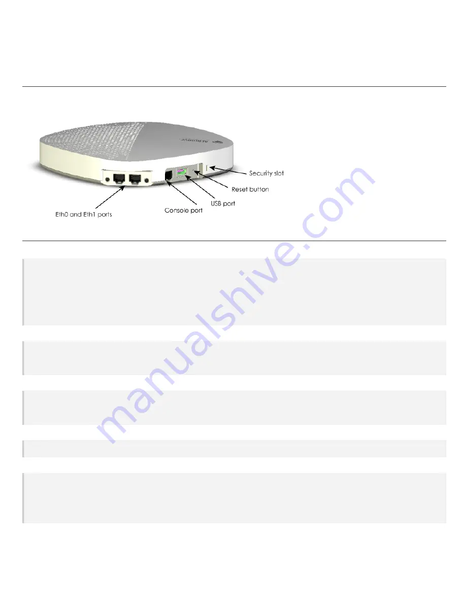
You can see the hardware components of the AP630 in the illustration below and read about them in the sections that follow.

Component Descriptions

Status Light

The round status light on the top corner of the device conveys operational states for system power, firmware updates, Ethernet and wireless inter-
face activity, and major alarms. The AP630 has a round status light on the top right corner of the chassis. At setup, this light cycles through the fol-
lowing sequence:

l

Dark

: There is no power to the device.

l

Amber (flashing)

: The device is performing a firmware upgrade. Do not power off the device during this process.

l

Amber (steady)

: The device has not established a successful CAPWAP connection, or is booting or shutting down.

l

White (steady)

: The device has successfully established a CAPWAP connection and is operating normally.

Ethernet Ports

The AP630 has two RJ45 Ethernet ports (Eth0 and Eth1) that automatically negotiate half- and full-duplex connections with the connecting
device. The ports are autosensing and adjust to straight-through and crossover standard Cat2, Cat5, Cat5e, or Cat6 Ethernet cables auto-
matically. The AP receives power through an Ethernet connection to the ETH0 port from PSE (power sourcing equipment) that is compatible with
the 802.3at and 802.3at standards.

Console Port

The AP630 has one RJ45 Console port. Use this port to make a serial connection between your management system and the AP. The man-
agement station from which you connect to the device must have a VT100 emulation program, such as Tera Term Pro © (a free terminal emu-
lator) or Hilgraeve HyperTerminal ® (provided with Windows ® operating systems from XP forward). The serial connection settings are: 9600 bits per
second, 8 data bits, no parity, 1 stop bit, no flow control.

USB Port

The AP630 has a USB port that you can use to connect USB-based beacons (iBeacon, for example) and IoT (Internet of Things) devices. To access
the port, remove the screw that secures the protective cover.

Reset Button

Use the Reset button to reset the device or restore the factory default settings. Insert a paper clip or similar tool into the Reset pinhole and press
the button. To reboot the device, press the button for 5 seconds. To return the configuration to the factory default settings, press it for at least 10
seconds. After releasing the button, the indicator light goes dark, and then glows steady amber while the firmware loads and the system per-
forms a self-test. After the software finishes loading and the AP has connected to HiveManager, the status indicator glows steady white.
To disable the reset button from resetting the configuration, enter this command:

no reset-button reset-config-enable

AP630 Hardware User Guide

Page 6

When this command is enabled, pressing the button for 5 seconds will still reboot the AP, but pressing it for more than 10 seconds will not reset its
configuration.

Summary of Contents for AP630

Page 1: ...o the country in which the AP will be deployed to meet regulatory requirements and for optimal wireless operation To do this follow these steps The country code selection is for World models only and is not available to FCC CAN and other country specific models Per FCC reg ulations all Wi Fi products marketed in the United States must be set to U S channels only 1 Power on the AP and allow it to f...

Page 2: ...ot intended for use by persons including children with reduced physical sensory or mental cap abilities or with lack of experience of knowledge unless they are given supervision or instruction concerning use of the devices by a person who is responsible for their safety Children should be supervised to ensure that they do not play with the devices Electrostatic discharge ESD can damage equipment a...

Page 3: ...the rail of a standard dropped ceiling grid AP630 Hardware User Guide Page 3 Once the bracket is secure youcan install the AP by aligning the red dot on the bracket with the red dot on the AP Keeping the dots aligned raise the AP up until the bracket fits into the circular depression in the bottom of the AP When the AP is firmly seated rotate it clockwise until it clicks in to place as shown here ...

Page 4: ...rface Use the following procedures and illustration 1 Drill two holes in the wall that are xx cm from center to center 2 Install wall mount screws provided what size AP630 Hardware User Guide Page 5 3 Attach the bracket to the wall using the holes in the mounting flanges as shown ...

Page 5: ...J45 Console port Use this port to make a serial connection between your management system and the AP The man agement station from which youconnect to the device must have a VT100 emulation program such as Tera Term Pro a free terminal emu lator or Hilgraeve HyperTerminal provided with Windows operating systems from XP forward The serial connection settings are 9600 bits per second 8 data bits no p...

Page 6: ...exing OFDM modulation l Rates Mbps 54 48 36 24 12 9 6 with auto fallback 802 11n l 2 4 2 48 and 5 150 5 850 GHz operating frequency l 802 11n modulation l Rates MCS0 MCS7 l 4x4 MIMO radio l HT20 HT40 support l A MPDU and A MSDU frame aggregation 802 11ac l 802 11ac modulation 256 QAM l 2 4 2 48 GHz MCS0 9 NSS 1 4 l 5 150 5 850 GHz operating frequency l Rates MCS0 MCS9 NSS 1 4 l 4x4 MIMO radio l VH...

Page 7: ... dBm MCS 4 5 16 dBm MCS 6 7 15 dBm MCS 8 9 14 dBm MCS 10 11 12 dBm 2 4 G Sensitivity 11b 1 Mbps 99 dB 11 Mbps 90 dB 11g 6 Mpbs 96 dB 36 Mpbs 84 dB 48 Mbps 80 dB 54 Mbps 78 dB HE20 MCS 0 95 dB MCS 1 91 dB MCS 2 89 dB MCS 3 86 dB MCS 4 83 dB MCS 5 79 dB MCS 6 77 dB MCS 7 76 dB MCS 8 72 dB MCS 9 70 dB MCS 10 67 dB MCS 11 64 dB AP630 Hardware User Guide Page 8 2 4 G ...

Page 8: ...CS 6 7 8 17 dBm MCS 9 16 dBm MCS 10 15 dBm MCS 11 14 dBm HE80 MCS 0 1 2 19 dBm MCS 3 4 5 18 dBm MCS 6 7 8 17 dBm MCS 9 16 dBm MCS 10 15 dBm MCS 11 14 dBm HE160 MCS 0 1 2 19 dBm MCS 3 4 5 18 dBm MCS 6 7 8 17 dBm MCS 9 16 dBm MCS 10 15 dBm MCS 11 14 dBm 5 G Sensitivity 11a 6 Mbps 94 db 36 Mbps 83 db 48 Mbps 79 db 54 Mbps 77 db HE20 MCS 0 94 db MCS 1 91 db MCS 2 88 db MCS 3 86 db AP630 Hardware User ...

Page 9: ... 3 83 db MCS 4 80 db MCS 5 76 db MCS 6 74 db MCS 7 73 db MCS 8 69 db MCS 9 67 db MCS 10 63 db MCS 11 60 db HE80 MCS 0 88 db MCS 1 85 db MCS 2 83 db MCS 3 80 db MCS 4 77 db MCS 5 73 db MCS 6 71 db MCS 7 69 db MCS 8 66 db MCS 9 64 db MCS 10 60 db MCS 11 57 db HE160 MCS 0 85 db MCS 1 82 db MCS 2 80 db MCS 3 77 db MCS 4 74 db MCS 5 70 db AP630 Hardware User Guide Page 10 ...

Page 10: ...condensing Regulatory Compliance Statements The regulatory compliance statements in this section apply to Aerohive AP630 devices Japan Indoor Use For Japan the AP630 is restricted for indoor use in the 5150 5350 MHz band only Japan Equipment VCCI B Statement Compliance Statement Europe EU Declaration of Conformity View this information online at www aerohive com support regulatory compliance Aeroh...

Page 11: ...erohive declara que o presente tipo de equipamento de rádio AP630 está em con formidade com a Diretiva 2014 53 UE l Romanian Romania Prin prezenta Aerohive declară că tipul de echipamente radio AP630 este în conformitate cu Directiva 2014 53 UE l Slovak Slovensky Aerohive týmto vyhlasuje že rádiové zariadenie typu AP630 je v súlade so smernicou 2014 53 EÚ l Slovenian Slovenija Aerohive potrjuje da...

Page 12: ...versiossa l 802 11b g n ac 2 4 GHz band 2412 2472 MHz EIRP 20 dBm l 802 11 a ac n ax 5 GHz band 5150 5350 MHz EIRP 23 dBm 5500 5720 MHz EIRP 30 dBm l BLE 2402 2480 MHz EIRP 10 dBm French Français Ce produit prend en charge les fréquences radio et les niveaux de puissance suivants dans la version EU l 802 11b g n ac 2 4 GHz band 2400 2483 MHz EIRP 20 dBm l 802 11a ac n ax 5 GHz band 5150 5350 MHz E...

Page 13: ...equencies and power levels in the EU version l 802 11b g n ac 2 4 GHz band 2400 2483 MHz EIRP 20 dBm l 802 11a ac n ax 5 GHz band 5150 5350 MHz EIRP 23 dBm 5500 5725 MHz EIRP 30 dBm 5725 5850 MHz 14 dBm l BLE 2402 2480 MHz EIRP 10 dBm Slovak Slovensky Tento produkt podporuje nasledujúce rádiové frekvencie a úrovne napájania vo verzii EÚ l 802 11b g n ac 2 4 GHz band 2400 2483 MHz EIRP 20 dBm l 802...

Page 14: ...imale de 11 28 cm des personnes oudes animaux Restrictions 5150 5250 MHz pour usage intérieur seulement German Deutsch Um die Anforderungen an die Strahlenbelastung zuerfüllen sollten diese Geräte in einem Abstand von 11 28 cm von Per sonen oder Tieren installiert werden Einschränkungen 5150 5250 MHz nur für den Innenbereich Greek Ελληνική Για την κάλυψη των απαιτήσεων έκθεσης σε ακτινοβολία οι συ...

Page 15: ...en this equipment and receiving equipment l Connect this equipment into an outlet on a circuit different from that to which the receiving equipment is connected l Consult the dealer or an experienced radio or TVtechnician for help FCC Caution Any changes or modifications not expressly approved by the party responsible for compliance could void the user s authority to operate this equipment This de...

Page 16: ...complies with IC radiation exposure limits set forth for an uncontrolled environment This equipment should be installed and oper ated with minimum distance 28 cm between the radiator and people or animals Déclaration d exposition aux radiations Cet équipement est conforme aux limites d exposition aux rayonnements IC établies pour un environnement non contrôlé Cet équipementdoit être installé et ut...

Reviews: