AERMEC WRL 200 Installation Manual Download Page 22

22

COMMISSIONING - WARNINGS

COMMISSIONING - WARNINGS

Please note that, on request by the Aermec customer or the legitimate 

owner of the machine, the units in this series can be started up by 

the AERMEC After-Sales Service in your area

 (valid only on ITALIAN 

territory). 

The start of operation must be scheduled in advance based 

on the time frame for the completion of works for the system. Prior to the 

intervention, all other works (electrical and hydraulic hook-ups, priming 

and bleeding of air from the system) must have been completed.

START-UP

OPERATIONS TO BE PERFORMED WITH NO VOLTAGE PRESENT

 ATTENTION 

the unit is not working:

Check:

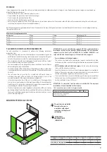
-  All safety conditions have been respected

-  The unit is correctly fixed to the support surface

-  The minimum technical spaces have been respected 

-  That the main power supply cables have appropriate cross-section, 

which can support the total consumption of the unit. (see electric 

data sections) and that the unit has been duly connected to the 

ground.

-  That all the electrical connections have been made correctly and all 

the terminals adequately tightened.

-   Check for refrigerant gas leaks, especially near the pressure points 

of pressure gauges, pressure transducers and pressure switches. 

(vibrations during transport may have loosened the connections).

OPERATIONS TO BE PERFORMED WITH THE UNIT LIVE


ATTENTION 

the unit is still not working:

-  Supply power to the unit by turning the master switch to the ON 

position.

-  Use a tester to verify that the value of the power supply voltage to 

the phases is equal to 400V ± 10%; also verify that the unbalance 

between phases is no greater than 3%.

-  Check that the connections made by the installer are in compliance 

with the documentation.

-  Verify that the resistor of the compressor sump is working by 

measuring the increase in temperature of the oil pan. The resistance/s 

must function for at least 12 hours before start-up of the compressor 

and in any event, the temperature of the oil pan must be 10-15°C 

higher than room temperature.

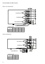
HYDRAULIC CIRCUIT CONTROLS

-  Check that all hydraulic connections are made correctly, that the 

plate indications are complied with and that a mechanical filter has 

been installed in each inlet heat exchanger. 

(Mandatory component 

for warranty to be valid).

-  Make sure that the circulation pump/s is operating and that the 

water flow rate is sufficient to close the contact of the flow switch, if 

installed.

-  Check the water flow rate, measuring the pressure difference 

between inlet and outlet of the evaporator and calculate the flow rate 

using the evaporator pressure drop tables present in this manual.

-  Check the correct functioning of the flow meters if installed. Closing 

the cut-off valve at the output of the heat exchanger; the unit control 

panel must show the block. Finally re-open the valve and rearm the 

block

COMMISSIONING

-  Once all the aforementioned checks have been carried out, the unit 

can be commissioned

-  Close the door of the electrical panel.

-  Set the unit main switch to ON, the unit will start after a few minutes

OPERATIONS TO BE PERFORMED WITH MACHINE ON

 ATTENTION 

the unit is working:

Check:

-   That the compressor input current is lower than the maximum 

indicated in the electrical data table.

-   Before starting the unit, check that the compressor rotates in the 

correct direction through a three-phase protection. The spiral 

compressors compress in one direction of rotation only. Therefore, 

it is essential for the phase of the three-phase spiral compressors 

to be correctly connected (the correct direction of rotation can be 

controlled when the pressure on the intake side decreases and that 

on the flow side increases with the compressor in operation). If the 

connection is incorrect, the direction of rotation is reversed: this 

causes a loud noise and the reduction of current consumption. In this 

case, the protection system inside the compressor activated turning 

off the unit. To solve the problem, disconnect and swap the wires 

between two of the phases, then connect the three-phases again.

-   That the voltage value lies within the pre-fixed limits and that 

unbalance between the three phases (three-phase power supply) is 

not above 3%.

If having to take measurements and perform checks that require the 

machine to run, you must:  

-  make sure that any remote control systems are disconnected; 

however, keep in mind that the PLC on the machine controls its 

functions and can enable and disable the components creating 

hazardous situations (e.g. power and rotate the fans and their 

mechanical drive systems). 

-  Operate with the electrical board open the shortest time possible

-  Close the electrical board as soon as the single measurement or 

control is performed  

ATTENTION

The anti-freeze set temperature can only be varied by an authorised 

after-sales centre and only after having checked that there is a suitable 

% of anti-freeze solution in the water circuit.

Whenever this alarm intervenes, call the nearest authorised after-sales 

service immediately

- Control of the water flow rate alarm, the unit provides for the 

management of a flow rate alarm controlled by a differential pressure 

switch or flow switch if provided. This type of safety device intervenes 

after the first 30 seconds of pump functioning, if the water flow rate is 

not sufficient. The intervention stops the compressor and the pump 

itself.

Summary of Contents for WRL 200

Page 1: ...w w w a e r m e c c o m T r a n s l a t i o n f r o m o r i g i n a l I n s t a l l a t i o n m a n u a l EN WRL WRL H 200 400 500 2 2 0 5 5 8 9 0 7 0 0 _ 0 5 WATER WATER CHILLERS HEAT PUMP ...

Page 2: ......

Page 3: ...EC products are synonymous with Safety Quality and Reliability The data may undergo modifications considered necessary for the improvement of the product at any time and without the obligation for any notice thereof Thank you once again AERMEC S p A This marking indicates that this product should not be disposed with other household wastes throughout the EU To prevent possible harm to the environm...

Page 4: ...OLING ONLY 12 WRLH 200 400 HEAT PUMP 13 WRLH 500 HEAT PUMP 13 WEIGHTS AND BARYCENTRES 14 ELECTRICAL CONNECTIONS 16 ELECTRICAL DATA 17 PUMPS ELECTRICAL DATA 17 STANDARD RATINGS 18 HEAT PUMP WATER SIDE INVERSION NO PUMP VERSION 18 HEAT PUMP REFRIGERANT SIDE INVERSION H NO PUMP VERSION 18 OPERATING LIMITS WRL 19 OPERATING LIMITS WRL H 20 ELECTRIC POWER CONNECTION TO THE ELECTRICAL MAINS 21 COMMISSION...

Page 5: ...5 CERTIFICATIONS COMPANY CERTIFICATIONS PERFORMANCE CERTIFICATIONS SAFETY CERTIFICATIONS ...

Page 6: ...necessary repairs The installation must comply with the requirements of EN378 3 and the local current regulations In particular indoor installation must ensure adequate ventilation and provide refrigerant detectors when necessary The machine must not be installed in environments with risk of explosion but in a suitable place In particular if intended for indoor use it cannot be installed outdoors ...

Page 7: ...xtures with ethylene glycol propylene in a maximum concentration of 30 The machine must only be employed for the use for which it was made any other use can be dangerous and void the warranty PREVENTIONS Make sure that the protections of mobile elements are correctly in place before restarting the unit Fans motors and belt drives may be in motion always wait for them to stop and take appropriate p...

Page 8: ...ied corresponds to the order and delivery note Product identification The Aermec products can be identified by the packaging label bearing the identification data of the product and by the technical plate bearing the performance and technical data of your unit If the product is damaged send a registered letter with the details of the problem to the shipping company within 48 working hours from del...

Page 9: ... of frost of the soil It is always advisable to build a support base separate from the main building to avoid the transmission of vibrations Stationary appliance for normal applications the rigidity of the unit and the positioning of point loads allow for an installation that minimises vibrations In the case of installations requiring particularly low vibration levels you can use the anti vibratio...

Page 10: ...IONS WRL WRL H 200 400 DIMENSIONS WRL WRL H 500 C C A B A1 A A1 B1 B B1 C C A B A1 A A1 B1 B B1 Model U M 200 400 A in 31 5 31 5 A1 33 3 33 3 B 50 0 50 0 B1 54 3 54 3 C 52 0 52 0 Model U M 500 A in 31 5 A1 33 3 B 50 0 B1 54 3 C 81 1 ...

Page 11: ...11 DIMENSIONS WRL WRL H 200 400 DIMENSIONS WRL WRL H 500 ANTI VIBRATION POSITION D D E E F F D E F D E F Model U M 200 400 D in 3 0 3 0 E 46 1 46 1 F 3 0 3 0 Model U M 500 D in 3 1 E 74 8 F 3 1 ...

Page 12: ...00 IN OUT Evaporator 2 2 Condenser 2 2 Desuperheater 1 1 WRL 200 400 COOLING ONLY WRL 500 COOLING ONLY IN OUT OUT IN OUT IN Electrical alimentation EVAPORATOR CONDENSER DESUPERHEATER Electrical alimentation DESUPERHEATER EVAPORATOR CONDENSER 6 3 in 3 3in 3 4 in 10 9 in 10 9 in 10 9 in 17 2 in 9 7 in 3 6 in 3 0 in 3 0 in 5 0 in 3 7 in 5 8 in 5 8 in 4 5 in 11 8 in 3 4 in 3 3 in ...

Page 13: ...OUT Geothermic side 2 2 2 2 System side 2 2 2 2 Desuperheater 1 1 1 1 CONNECTIONS Ø WRL 500 IN OUT Geothermic side 2 2 System side 2 2 Desuperheater 1 1 WRLH 200 400 HEAT PUMP WRLH 500 HEAT PUMP GEOTHERMIC SIDE SYSTEM SIDE DESUPERHEATER 6 3 in 3 3in 3 4 in 10 9 in 10 9 in 10 9 in 17 2 in 9 7 in 3 6 in 3 0 in 3 0 in 5 0 in 3 7 in 5 8 in 5 8 in 4 5 in 11 8 in 3 4 in 3 3 in ...

Page 14: ...e of gravity Gx Gy Gx Gy A B C D lb in in lb in in 200 804 15 6 25 6 858 15 5 26 2 27 23 27 23 400 966 15 6 23 7 1020 15 4 24 3 29 25 25 22 500 1289 15 0 40 7 1359 14 9 41 7 27 22 28 23 WRL H Empty weights Running weights Percentage weight distribution on supports Weights Centre of gravity Weights Centre of gravity Gx Gy Gx Gy A B C D lb in in lb in in 200 715 15 4 23 6 767 14 9 24 4 29 24 26 21 4...

Page 15: ...27 23 400 966 15 9 23 7 1017 15 5 24 3 29 25 25 22 500 1316 15 8 41 0 1390 15 6 42 0 26 23 27 24 SYSTEM EXTERNAL SIDE PUMPS VERSION WRL Empty weights Running weights Percentage weight distribution on supports Weights Centre of gravity Weights Centre of gravity Gx Gy Gx Gy A B C D lb in in lb in in 200 892 15 9 27 1 946 15 7 27 6 25 22 28 25 400 1080 15 8 25 6 1134 15 7 26 0 26 24 26 24 500 1413 15...

Page 16: ...e considered responsible for any damage caused by the lack of or ineffective appliance earth connection For units with three phase power supply check the correct connection of the phases ATTENTION All the electrical operations must be carried out by personnel in possession of the necessary qualifications by law suitably trained and informed on the risks related to these operations The characteristic...

Page 17: ...0V 3 60 Hz LRA A V 118 4 149 2 183 2 N V 122 4 153 2 187 2 U 122 4 153 2 187 2 N U 126 4 157 2 191 2 MCA A V 35 0 45 0 60 0 N V 35 0 50 0 60 0 U 35 0 50 0 60 0 N U 40 0 60 0 70 0 MOP A V 40 0 60 0 75 0 N V 45 0 60 0 75 0 U 45 0 60 0 75 0 N U 50 0 60 0 80 0 Electrical data 575V 3 60 Hz LRA A V 92 4 99 7 134 7 N V 95 6 102 9 137 9 U 95 6 102 9 137 9 N U 98 8 106 1 141 1 MCA A V 25 0 35 0 50 0 N V 30...

Page 18: ...at exchanger Condenser Min flow rate gpm 11 89 11 89 41 83 Max flow rate gpm 73 97 73 97 211 34 Minimum water operating pressure PN psi 7 3 7 3 7 3 Maximun water operating pressure PN psi 116 0 116 0 116 0 Reference data in cooling operation Evaporator Water temperature in out 54 0 44 1 F Condenser Water temperature in out 84 9 94 6 F Reference data in cooling operation Evaporator Water temperatur...

Page 19: ...envelope It is recommended to consider these temperatures when transporting in containers OPERATING COOLING MODE RANGE Key A Processed water temperature source side F B Water produced system side F 1 Operation valve Y 2 Operation valve X 0 20 40 60 80 100 111 2 131 120 140 F 0 10 17 6 30 39 2 50 60 64 4 70 F 95 131 B A 1 2 OPERATING HEATING MODE RANGE Key A Water produced system side F B Processed...

Page 20: ...pe It is recommended to consider these temperatures when transporting in containers OPERATING COOLING MODE RANGE Key A Processed water temperature source side F B Water produced system side F 1 Operation valve X 0 0 20 0 40 0 60 0 80 0 100 0 120 0 140 0 F 30 0 35 0 39 2 45 0 50 0 55 0 60 0 64 4 70 0 95 0 131 0 131 0 F B 1 A OPERATING HEATING MODE RANGE Key A Water produced system side F B Processe...

Page 21: ...r exclusively to the wiring diagram supplied with the unit Remove any protections from the cable fixing points For the functional connection of the unit take the power supply cable to the electric control board inside the unit and connect it to clamps L1 L2 L3 N if present and PE respecting the polarities L1 L2 L3 and N as phases and PE as grounding Ensure that all protections removed for the elec...

Page 22: ...ssure drop tables present in this manual Check the correct functioning of the flow meters if installed Closing the cut off valve at the output of the heat exchanger the unit control panel must show the block Finally re open the valve and rearm the block COMMISSIONING Once all the aforementioned checks have been carried out the unit can be commissioned Close the door of the electrical panel Set the ...

Page 23: ... accident prevention shoes etc Equip yourself with tools in good condition and make sure to have fully understood the instructions before using them For outdoor units do not perform interventions in dangerous weather conditions such as rain snow fog etc The cooling circuit contains under pressure refrigerant gas any operation must be performed by competent personnel in possession of the authorisat...

Page 24: ...essor evaporator condensing coil or any other heavy element make sure that the lifting devices are compatible with the weight to be handled In air units with independent compressor compartment do not access the fan compartment without having first disconnected the machine through the isolator on the board and having placed a sign reading Do not turn on maintenance in progress Always and only use o...

Page 25: ...ressor inlet and outlet pipes Avoid using metratast that require the operator to near the machine cooling circuit Access the machines and acquire the measurements keeping AWAY from the under pressure parts of the cooling circuit As soon as the measurements are taken turn off the machine remove the instruments and close the cooling circuit compartment The thermostatic valve must be calibrated with ...

Page 26: ...ention to under pressure containers In this case replace them of intervene with specific products General cleaning of the unit Bleed the hydraulic circuit and the heat exchangers the simultaneous presence of air and water reduces yield and can benefit the arising of rust INTERVENTIONSTO COOLING CIRCUIT Functioning at full load Overheating temperature measurement Subcooling temperature measurement ...

Page 27: ... and it must be removed from the installation in order to minimise the environmental impact respect the following disposal requirements Therefrigerantgasmustbefullyrecoveredinspecialcontainers and brought to collection centres by specialised personnel having the necessary qualification The lubricating oil in the compressors and cooling circuit must be recovered and brought to collection centres Th...

Page 28: ...ture development 14 Soft start Without soft start S With soft start 5 15 Power supply 6 230V 3 60Hz with magnet circuit breakers 7 460V 3 60Hz with magnet circuit breakers 8 575V 3 60Hz with magnet circuit breakers 9 208V 3 60Hz with magnet circuit breakers 1 Water produced up to 39 2 F 2 Water produced up to 39 2 F For different temperature please contact the factory 3 Water produced from 39 2 F ...

Page 29: ......

Page 30: ......

Page 31: ......

Page 32: ...0 B e v i l a c q u a V R I t a l y T e l 3 9 0 4 4 2 6 3 3 1 1 1 F a x 3 9 0 4 4 2 9 3 5 7 7 m a r k e t i n g a e r m e c c o m w w w a e r m e c c o m DOWNLOAD THE LATEST VERSION http www aermec com qrcode asp q 6452 2 2 0 5 5 8 9 0 7 0 0 _ 0 5 ...

Reviews: