background image

48

IVEDLJ 1107 - 4880900_01

Gli schemi elettrici sono soggetti ad un continuo aggiornamento, è obbligatorio quindi fare riferimento a quelli a bordo macchina.
A l l   w i r i n g   d i a g r a m s   a r e   c o n s t a n t l y   u p d a t e d .   P l e a s e   r e f e r   t o   t h e   o n e s   s u p p l i e d   w i t h   t h e   u n i t .
Nos schémas électriques étant constamment mis à jour, il faut absolument se référer à ceux fournis à bord de nos appareils.
Die Schaltpläne werden ständig aktualisiert, deswegen muss man sich stets auf das mit dem Gerät gelieferte Schaltschema beziehen.
El cableado de las máquinas es sometido a actualizaciones constantes. Por favor, para cada unidad hagan referencia a los esquemas suministrados con la misma.

LEGENDA • READING KEY • LEGENDE • LEGENDE • LEYENDA

SCHEMI ELETTRICI • WIRING DIAGRAMS • SCHEMAS ELECTRIQUES • SCHALTPLÄNE • ESQUEMAS ELÉCTRICOS

1

2

5

6

7

8

9

10

3

4

BL

NE

MA

RO

M

M

1

MV

BL

NE

MA

RO

MIN

MED

MAX

5

5

1

4

4

3

3

2

2

6

6

1

MV

M

BL

BL

COM - BL

L

NE

1

MA

VI

MAX - NE

2

GR

MED - MA

3

MA

MIN - RO

4

RO

5

C

MIN

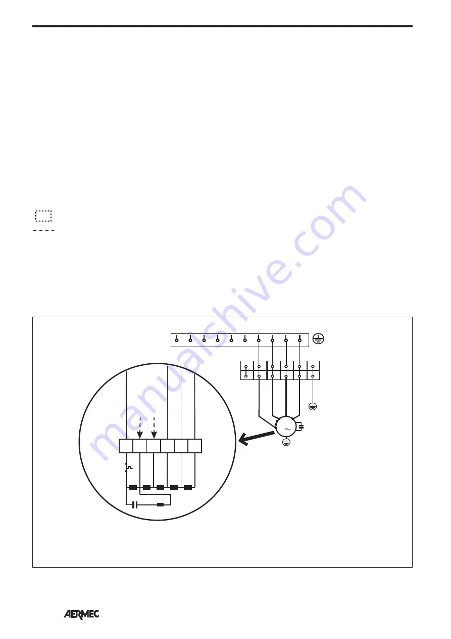
Le velocità disponibili sono numerate da 1 a 5 in ordine 
decrescente di velocità.
Le unità sono fornite con i collegamenti (3-4-5) come 
indicato in figura.
Per abilitare le velocità più alte spostare il collegamento 
ai morsetti 1 e/o 2.

VED

AR

 = 

Arancio 

BI

 = 

Bianco 

BL

 = 

Blu 

GR

 = 

Grigio 

GV

 = 

Giallo-Verde 

MA

 = 

Marrone 


NE

 = 

Nero 

RO

 = 

Rosso

AR

 = 

Orange 

BI

 = 

White 

BL

 = 

Blue 

GR

 = 

Grey 

GV

 = 

Yellow-green 

MA

 = 

Brown 


NE

 = 

Black 

RO

 = 

Red

AR

 = 

orange 

BI

 = 

blanc 

BL

 = 

bleu 

GR

 = 

gris 

GV

 = 

jaune-vert 

MA

 = 

marron 


NE

 = 

noir 

RO

 = 

rouge

AR

 = 

Orange 

BI

 = 

Weiß 

BL

 = 

Blau 

GR

 = 

Grau 

GV

 = 

Gelb/Grün 

MA

 = 

Braun 


NE

 = 

Schwarz 

RO

 = 

Rot

AR

 = 

Naranja 

BI

 = 

Blanco 

BL

 = 

Azul 

GR

 = 

Gris 

GV

 = 

Amarillo-Verde 

MA

 = 

Marrón 


NE

 = 

Negro 

RO

 = 

Rojo 

F

 = 

Fusibile • Fuse • Fusible  • Sicherung • Fusible

IG


= Interruttore generale • Master switch • Interrupteur général • Hauptschalter • Interruptor general 

M


=  Morsettiera • Control board • Bornier • Klemmleiste • Caja de conexiones 

MV


= Motore ventilatore • Fan motor • Moteur du ventilateur • Ventilatormotor • Motor ventilador 

PE


= Collegamento di terra • Earth connection • Mise à la terre • Erdung • Toma de tierra 

SA


= Sonda ambiente • Ambient probe • Sonde ambiante • Raumtemperaturfühler • Sonda ambiente 

SC


= Sonda ambiente • Control card • carte de contrôle • Steuerplatine • Tarjeta de control 

SW


= Sonda minima temperatura acqua • Minimum water temperature probe • Sonde de température minimale de l'eau 


  Sonde für Mindest-Wassertemperatur • Sonda mínima temperatura del agua

VC


= Valvola solenoide caldo • Solenoid valve hot • Vanne magnétique chaud 


  Magnetventil Heizbetrieb • Válvula solenoide para calor 

VF


= Valvola solenoide freddo • Solenoid valve cold • Vanne magnétique froid


  Magnetventil Kühlbetrieb • Válvula solenoide para frío 

 = Componenti non forniti • Components not supplied • Composants non fournis 
   Nicht lieferbare Teile • Componentes no suministrados 
 = Componenti forniti optional • Components supplied as optional extras • Composants fournis en option 
   Als Option lieferbare Teile • Componentes opcionales facilitados    
  = Collegamenti da eseguire in loco • Connections to be made on site • Branchements à effectuer sur les lieux
    Vor Ort auszuführende Anschlüsse • Conexiones que realizar in situ

Summary of Contents for VED Series

Page 1: ...ALLATION BEDIENUNGS UND INSTALLATIONSANLEITUNG MANUAL DE INSTRUCCIONES E INSTALACIÓN IVEDLJ 1107 4880900_01 VED VENTILCONVETTORE PER INSTALLAZIONE CANALIZZATA ORIZZONTALE E VERTICALE FAN COIL FOR HORIZONTAL AND VERTICAL DUCTED INSTALLATION VENTILO CONVECTEUR POUR INSTALLATION CANALISÉE HORIZONTALE ET VERTICALE GEBLÄSEKONVEKTOR FÜR KANAL HORIZONTAL UND VERTIKALEINBAU FAN COIL PARA INSTALACIÓN CANAL...

Page 2: ...MBOLI DI SICUREZZA CARRIAGE SAFETY SYMBOL TRANSPORT SIMBOLESES DE SECURITE TRANSPORT SICHERHEITSSYMBOLE TRANSPORTE SÍMBOLOS DE SEGURIDAD Italiano English Français Deutsche Español DIMENSIONI DIMENSIONS DONNEES DIMENSIONNELLES ABMESSUNGEN DIMENSIONES SCHEMI ELETTRICI WIRING DIAGRAMS SCHEMAS ELECTRIQUES SCHALTPLÄNE ESQUEMAS ELÉCTRICOS SOLUZIONE DEI PROBLEMI TROUBLESHOOTING SOLUTION DES PROBLÈMES PRO...

Page 3: ...es coûts dérivant de l utilisation de voitures avec échelle mécanique d échafaudages ou d autres systèmes de levée employés pour effectuer des interventions en garantie AERMEC S p A décline toute responsabilité pour tout dommage dû à une utilisation impropre de l appareil et à une lecture partielle ou superficielle des informations contenues dans ce manuel Les informations contenues dans ce manuel...

Page 4: ...la presente dichiariamo sotto la nostra esclusiva responsabilità che il prodotto VENTILCONVETTORE PER INSTALLAZIONE CANALIZZATA ORIZZONTALE E VERTICALE serie VED al quale questa dichiarazione si riferisce è conforme alle seguenti norme armonizzate CONFORMITY DECLARATION We the undersigned declare under our own exclusive responsibility that the product FAN COIL FOR HORIZONTAL ANDVERTICAL DUCTED INS...

Page 5: ...lare sull imballo per conoscere il numero di macchine impilabili Stacking control the packing to know the number of machines that can be stacked Empilement vérifier sur l emballage pour connaître le nombre d appareils pouvant être empilés Stapelung DieAnzahl der stapelbaren Geräte wird durch die Symbole auf denVerpackungen ermittelt Apilamiento observe en el embalaje para saber cuántos equipos pue...

Page 6: ... modulazione continua della velocità suddivisi in zone fino a 64 le pompe di circolazione fino a 12 e i recuperatori di calore con sonda di qualità dell aria fino a 3 ottimizzando le prestazioni in condizionamento e riscaldamento garantendo confort e risparmio energetico INDICE 7 8 9 10 11 12 13 46 48 65 Informazioni importanti Manutenzione Imballo Uso Descrizione Versioni Esempi di impianto Compo...

Page 7: ...O Lasciare sempre il filtro montato sul ventilconvettore durante il funzionamento altrimenti la polvere presente nell aria andrà a sporcare le superfici della batteria È NORMALE Nel funzionamento in raffrescamento può uscire del vapore acqueo dalla mandata del ventilconvettore Nel funzionamento in riscaldamento un leggero fruscio d aria può essere avvertibile in prossimità del ventilconvettore Tal...

Page 8: ...ra Filtro classe di filtrazione G3 Filtro dell aria in aspirazione facilmente estraibile per la pulizia periodica Accessori valvole a 3 vie 4 attacchi Accessori valvole a 2 vie per gli impianti a portata d acqua variabile Isolante interno classe 1 Pieno rispetto delle norme anti infortunistiche Facilità di installazione e manutenzione Flangia di mandata ricavata direttamente sull unità Caratterist...

Page 9: ...di mandata sono realizzate per raccordare il ventilconvettore a ogni tipo di canalizzazione dell aria La bocca di mandata comprende la flangia di raccordo SCARICO CONDENSA Ogni apparecchio è corredato di una bacinella raccolta condensa sia per l installazione verticale che per l installazione orizzontale La bacinella è dotata di 2 raccordi Øe 16mm per lo scarico della condensa I 2 raccordi sporgon...

Page 10: ...onsigliata C 65 Massima pressione d esercizio bar 8 Minima portata d acqua Batteria principale l h 300 300 300 300 300 300 300 300 Massima portata d acqua Batteria principale l h 3000 3000 3000 3000 3000 3000 3000 3000 Minima portata d acqua Batteria Solo Riscaldamento l h 200 100 200 100 Massima portata d acqua Batteria Solo Riscaldamento l h 2000 1500 2000 1500 Limiti di temperatura ambiente Ta ...

Page 11: ... sono dotati di motori a 5 velocità è possibile scegliere le 3 velocità di lavoro modificando i collegamenti nella scatola elettrica del motore I ventilconvettori sono forniti con i collegamenti alle velocità standard Consultare lo schema elettrico prima di modificare i collegamenti sul motore Nel caso sia installata la valvola a tre vie la sonda di minima temperatura dell acqua può essere install...

Page 12: ... componenti forniti come accessori verificarne la disponibilità ATTENZIONE Verificare che il pannello comandi sopporti il carico del motore elettrico altrimenti interporre tra il ventilconvettore ed il pannello comandi una interfaccia accessorio SIT3 ATTENZIONE Le unità equipaggiate con termostati serie VMF devono essere abbinate con una interfaccia accessorio VMF SIT Nell abbinamento dei pannelli...

Page 13: ...inella di raccolta condensa Togliere il coperchio di chiusura della batteria svitando le viti Togliere le viti che fissano la batteria e quindi estrarla Rimuovere i semitranciati dalla fiancata destra ATTENZIONE Prima di ruotare la batteria consultare lo schema di rotazione della batteria É importante che la batteria sia ruotata ed installata nel giusto verso Ruotare correttamente la batteria e fi...

Page 14: ...eed or continuous modulation of the speed divided into zones up to 64 circulation pumps up to 12 and heat recovery units with air quality sensor up to 3 optimising conditioning and heating performance to ensure comfort and energy savings INDEX 15 16 17 18 19 20 21 46 47 65 Important information Maintenance Packaging Use Description Versions System example Main components Description of components ...

Page 15: ...reas or venues requiring high hygiene standards DURING OPERATION Always leave the filter fitted on the fan coil during operation otherwise dust in the air could soil the coil surface area WHAT IS NORMAL In the cooling operation water vapour may be present in the air delivery of the fan coil In the heating operation a slight hiss might be heard close to the fan coil Sometimes the fan coil might giv...

Page 16: ...filtration class G3 Air intake filter easily removable for periodic cleaning Accessories for 3 way valve with 4 connections Accessories 2 way valve for the systems to variable water flow rate Internal insulating class 1 Full compliance with the accident pre vention standards Ease of installation and maintenance Discharge flange incorporated in the unit Main features of the VED fancoils Vertical in...

Page 17: ...ed at the rear The inlets and outlets are designed to connect the fancoil to all types of air ducting The outlet includes the coupling flange CONDENSATE DISCHARGE Every device is equipped with a con densate collection tray for both vertical and horizontal installation The tray has 2 fittings Ø 16mm for the discharge of condensate The 2 fittings protrude from the side of the unit HYDRAULIC CONNECTI...

Page 18: ... temperature C 80 Maximum recommended water inlet temperature C 65 Maximum operating pressure bar 8 Minimum water flow rate Main coil l h 300 300 300 300 300 300 300 300 Maximum water flow rate Main coil l h 3000 3000 3000 3000 3000 3000 3000 3000 Minimum water flow rate Heating Only Coil l h 200 100 200 100 Maximum water flow rate Heating Only Coil l h 2000 1500 2000 1500 External temperature lim...

Page 19: ...th air ducting The VED fancoils are equipped with 5 speed motors 3 operating speeds of which can be selected by changing the connections in the electrical box of the motor The fancoils are provided with connections to the standard speed See the wiring diagram before changing the motor connections If a three way valve is installed the mini mum water temperature sensor can be installed in two locati...

Page 20: ...s supplied as acces sories check availability WARNING Make sure the control panel supports the load of the electric motor otherwise placed an SIT3 inter face accessory between the fan and the control panel WARNING The units that are equipped with VMF series thermostats must be combined with an VMF SIT interface accessory When combining to control panels the relative wiring diagram must be respecte...

Page 21: ... Remove the condensate drip tray Undo the screws and remove the coil cover Remove the screws securing the coil then remove the coil Remove the push outs on the right hand side WARNING Consult the coil rotation diagram before rotating the coil It is important that the coil is installed and rotated in the right direction Rotate the coil correctly and secure it with the previously removed screws The ...

Page 22: ...à modulation continue de la vitesse divisés en zones jusqu à 64 des pompes de circulation jusqu à 12 et des récupérateurs de chaleur avec sonde de qualité de l air jusqu à 3 en optimisant les performances de climatisation de l air et du chauffage pour assurer le confort et l économie d énergie INDEX 23 24 25 26 27 28 29 46 47 65 Informations importantes Entretien Emballage Utilisation Description ...

Page 23: ...NCTIONNEMENT Pendant la marche laisser le filtre toujours monté sur le ventilo convecteur car autre ment la poussière qui se trouve dans l air peut salir la surface de la batterie IL EST NORMAL Pendant le fonctionnement en mode refroidissement de la vapeur d eau peut sortir du refoulement du ventilo convecteur Pendant le fonctionnement en mode chauffage on peut entendre un léger bruissement d air ...

Page 24: ...se de filtration G3 Filtre à air à l aspiration facilement extractible pour le nettoyage périodique Accessoires pour vannes à 3 voies et 4 raccords Accessoires pour vannes à 2 voies pour les installations à débit d eau variable Isolant interne classe 1 Plein respect des normes de prévention des accidents Facilité d installation et d entretien Bride de refoulement installée directe ment sur l unité...

Page 25: ...ration et de soufflage sont réalisées pour raccorder le ventilo convec teur à tout type de canalisation de l air La bouche de soufflage comprend la bride de raccord ÉVACUATION DES CONDENSATS Chaque appareil est équipé d un bac de récupération des condensats tant pour l installation verticale que pour celle hori zontale Le bac est doté de 2 raccords Ø 16 mm pour l évacuation des condensats Les 2 ra...

Page 26: ...empérature maximale de l eau à l entrée C 80 Température maximale conseillée de l eau à l entrée C 65 Pression de service maximale bars 8 Débit d eau minimal Batterie principale l h 300 300 300 300 300 300 300 300 Débit d eau maximal batterie principale l h 3000 3000 3000 3000 3000 3000 3000 3000 Débit d eau minimal batterie chauffage seul l h 200 100 200 100 Débit d eau maximal Batterie chauffage...

Page 27: ...ns d air Les ventilo convecteurs VED sont équi pés de moteurs à 5 vitesses il est possible de sélectionner les 3 vitesses de fonctionnement en modifiant les connexions dans l armoire électrique du moteur Les ventilo convecteurs sont fournis avec les connexions aux vitesses standard Consulter le sché ma électrique avant de modifier les connexions du moteur Si la vanne à trois voies est installée la...

Page 28: ... association avec des composants fournis comme acces soires vérifier leur disponibilité ATTENTION Vérifier si le panneau de commande supporte la charge du moteur électrique interposer autrement une interface accessoire SIT3 entre le ventilo convecteur et le panneau de commande ATTENTION Les unités équipées de thermostats série VMF doivent être associées avec une interface acces soire VMF SIT Pour ...

Page 29: ...meture avant Retirer le bac de récupération des condensats Dévisser les vis respectives et retirer le couvercle de fermeture de la batterie Retirer les vis qui fixent la batterie puis l extraire Retirer les parties prédécoupées du flanc droit ATTENTION Avant de tourner la batterie consulter le schéma de rotation Il est important que la batterie soit tournée et installée dans le sens correct Tourne...

Page 30: ...vektorennetz mit mehrstufiger Drehzahl oder permanenter Drehzahlmodulation das in bis zu 64 Bereiche unterteilt ist bis zu 12 Umlaufpumpen und bis zu 3 Wärme rückgewinner mit Fühler zur Prüfung der Luftqualität Dies garantiert optimale Leistungen bei der Klimatisierung und Heizung hohen Komfort und Energieeinsparung INDEX 31 32 33 34 35 36 37 46 47 65 Wichtige Informationen Wartung Verpackung Verw...

Page 31: ...requentiert sind oder einen hohen Hygienestandard erfordern WÄHREND DES BETRIEBS Lassen Sie während des Betriebs den Filter stets am Gebläsekonvektor montiert anderenfalls verschmutzt der in der Luft enthaltene Staub die Wärmetauschfläche ES IST NORMAL Beim Kühlbetrieb kann Wasserdampf aus dem Vorlauf des Gebläsekonvektors austreten Beim Heizbetrieb kann ein leichter Luftzug in der Nähe des Gebläs...

Page 32: ...edrige Geräuschemission ausgelegt sind Filter Filterklasse G3 Ansaugluftfilter leicht herausnehmbar für die regelmässige Reinigung Zubehörteile für 3 Wege Ventil mit 4 Anschlüssen Zubehörteile für 2 Wege Ventil bei Anlagen mit variablem Wasserdurchsatz Innenisolierung Klasse 1 Gerätekonzeption gemäß Arbeitsschutz vorschriften Problemlose Installation und Wartung Direkt an der Einheit angebrachter ...

Page 33: ...so gestaltet dass der Gebläsekonvektor an jede Art der Luftkanalisierung ange schlossen werden kann Der Zuluftstutzen beinhaltet den Anschluss flansch KONDENSATABLASS Jedes Gerät verfügt sowohl bei der senk rechten als auch bei der waagerechten Installation über eine Kondensatauffang schale Das Auffangbecken verfügt über 2 Anschlüsse Øe 16mm zum Ablassen des Kondenswassers Die 2 Anschlüsse ragen a...

Page 34: ...fohlene maximale Wassereintrittstemperatur C 65 Maximaler Betriebsdruck bar 8 Mindestwasserdurchsatz Hauptwärmetauscher l h 300 300 300 300 300 300 300 300 Maximaler Wasserdurchsatz Hauptwärmetauscher l h 3000 3000 3000 3000 3000 3000 3000 3000 Mindestwasserdurchsatz Wärmetauscher für reinen Heizbetrieb l h 200 100 200 100 Maximaler Wasserdurchsatz Wärmetauscher für reinen Heizbetrieb l h 2000 150...

Page 35: ...n können 3 als Betriebsgeschwindig keiten ausgewählt werden indem die Anschlüsse im Schaltkasten des Motors verändert werden Die Gebläsekonvek toren werden mit den Anschlüssen an die Standard Drehzahlen geliefert Zie hen Sie den Schaltplan zu Rate bevor Sie die Anschlüsse am Motor ändern Sollte das 3 Wege Ventil installiert sein kann der Fühler für die Wassermindest temperatur in zwei Stellungen i...

Page 36: ...ert werden Überprüfen Sie daher deren Verfügbarkeit ACHTUNG Überprüfen Sie ob das Bedienelement der Ladung des Elektro motors standhält ansonsten muss zwi schen dem Gebläsekonvektor und dem Bedienelement eine SIT3 Schnittstelle Zubehör zwischengeschaltet werden ACHTUNG Die Geräte die mit einem Thermostat der Serie VMF ausgerüstet sind müssen mit einer Zubehör Schnitt stelle VMF SIT kombiniert werd...

Page 37: ...e die Abdeckung des Wär metauschers durch Lösen der Schrauben Entfernen Sie die Befestigungsschrau ben des Wärmetauschers und ziehen Sie ihn heraus Entfernen Sie die Vorstanzungen vom rechten Seitenteil ACHTUNG Vor dem Drehen des Wär metauschers das Rotationsschema des Wärmetauschers zu Rate ziehen Es ist wichtig dass der Wärmetauscher in der richtigen Richtung gedreht und installiert ist Drehen S...

Page 38: ...ntinua de la velocidad subdivididos en zonas hasta 64 las bombas de circulación hasta 12 y los recuperadores de calor con sonda de calidad del aire hasta 3 optimizando las prestaciones en acondicionamiento y calentamiento garantizando confort y ahorro energético ÍNDICE 39 40 41 42 43 44 45 46 47 65 Información importante Mantenimiento Embalaje Uso Descripción Versiones Ejemplos de instalación Comp...

Page 39: ...igiene elevado DURANTE EL FUNCIONAMIENTO Deje el filtro montado en el fan coil siem pre que esté en funcionamiento ya que si no el polvo del aire ensuciará las superfi cies de la batería ES NORMAL Durante el funcionamiento en frío puede salir vapor de agua por el canal de envío del fan coil Durante el funcionamiento en calenta miento puede sentirse un ligero silbido del aire en las proximidades de...

Page 40: ...ón para la limpieza periódica Accesorios válvulas de 3 vías y 4 conexiones Accesorios válvulas de 2 vías para las instalaciones con caudal de agua variable Aislante interno clase 1 Pleno respeto de las normas de preven ción de accidentes Facilidad de instalación y mantenimiento Brida de ventilación obtenida directamente en la unidad Características principales de los fan coils VED Instalación vert...

Page 41: ...ermiten conectar el fan coil a cual quier tipo de canalización del aire La boca de ventilación comprende la brida de racor DESCARGA DEL AGUA DE CONDENSACIÓN Cada equipo cuenta con una cubeta para recoger el agua de condensación tanto para la instalación vertical como para la instalación horizontal La cubeta tiene 2 racores Ø 16 mm para la descarga del agua de condensación Los 2 racores sobresalen ...

Page 42: ...entrada de agua C 80 Máxima temperatura de entrada de agua recomendada C 65 Presión máxima de funcionamiento bar 8 Mínimo caudal de agua Batería principal l h 300 300 300 300 300 300 300 300 Máximo caudal de agua Batería principal l h 3000 3000 3000 3000 3000 3000 3000 3000 Mínimo caudal de agua Batería sólo calor l h 200 100 200 100 Máximo caudal de agua Batería sólo calor l h 2000 1500 2000 1500...

Page 43: ...os de trabajo modifican do las conexiones en la caja eléctrica del motor Los fan coils se entregan con las conexiones correspondientes a las velocidades estándar Consultar el esquema eléctrico antes de modificar las conexiones en el motor Si está instalada la válvula de tres vías la sonda de temperatura mínima del agua puede instalarse en dos posiciones en su alojamiento en la batería al tubo de v...

Page 44: ...cesorios controlar la disponibilidad de los mismos ATENCIÓN Controlar que el tablero de mandos soporte la carga del motor eléctrico caso contrario colocar una interfaz accesorio SIT3 entre el fan coil y el tablero de mandos ATENCIÓN Las unidades equipadas con termostatos de la serie VMF se deben asociar con una interfaz acce sorio VMF SIT Al asociar los tableros de mandos se debe respetar el esque...

Page 45: ...colección del agua de condensación Retirar la tapa de cierre de la batería desenroscando los tornillos Retirar los tornillos de fijación de la batería y luego extraerla Retirar los semitroquelados del lateral derecho ATENCIÓN Antes de girar la batería con sultar el esquema de rotación de la batería Es importante girar la batería en el senti do correcto e instalarla correctamente Girar la batería y...

Page 46: ...embra Ø 3 4 G 3 4 G 3 4 G 3 4 G 3 4 G 3 4 G 3 4 G 3 4 G Attacchi idraulici batteria per solo riscaldamento femmina Heating only coil water connections female Raccords hydrauliques de la batterie pour chauffage seul femelle Wasseranschlüsse für Wärmetauscher für reinen Heizbetrieb Innengewinde Conexiones hidráulicas batería sólo calor hembra Ø 1 2 G 1 2 G 1 2 G 1 2 G Attacchi scarico condensa diame...

Page 47: ...l hembra Ø 3 4 G 3 4 G 3 4 G 3 4 G 3 4 G 3 4 G 3 4 G 3 4 G Attacchi idraulici batteria per solo riscaldamento femmina Heating only coil water connections female Raccords hydrauliques de la batterie pour chauffage seul femelle Wasseranschlüsse für Wärmetauscher für reinen Heizbetrieb Innengewinde Conexiones hidráulicas batería sólo calor hembra Ø 1 2 G 1 2 G 1 2 G 1 2 G Attacchi scarico condensa di...

Page 48: ...c BL bleu GR gris GV jaune vert MA marron NE noir RO rouge AR Orange BI Weiß BL Blau GR Grau GV Gelb Grün MA Braun NE Schwarz RO Rot AR Naranja BI Blanco BL Azul GR Gris GV Amarillo Verde MA Marrón NE Negro RO Rojo F Fusibile Fuse Fusible Sicherung Fusible IG Interruttore generale Master switch Interrupteur général Hauptschalter Interruptor general M Morsettiera Control board Bornier Klemmleiste C...

Page 49: ... máquinas es sometido a actualizaciones constantes Por favor para cada unidad hagan referencia a los esquemas suministrados con la misma SCHEMI ELETTRICI WIRING DIAGRAMS SCHEMAS ELECTRIQUES SCHALTPLÄNE ESQUEMAS ELÉCTRICOS 10k SA 4 3 2 1 Only master CN11 SA 1 E0 1 Slave 1 5 TTL SW 30 m MAX E0 1 Master VC E4 BL GR MA AR V1 V2 V3 V1 V2 V3 L N N PH VMF SIT3 F 2A INPUT OUTPUT MIN MED MAX 10k VH BL GR M...

Page 50: ...a cada unidad hagan referencia a los esquemas suministrados con la misma SCHEMI ELETTRICI WIRING DIAGRAMS SCHEMAS ELECTRIQUES SCHALTPLÄNE ESQUEMAS ELÉCTRICOS 10k SA 4 3 2 1 Only master SW VH VC E4 V1 V2 V3 V1 V2 V3 L N N PH VMF SIT3 F 2A INPUT OUTPUT MIN MED MAX 10k BL GR MA AR RO 230V 50Hz PE L N IG VMF SIT3 VMF E1 VMF E4 E1 CN9 JP1 CN11 PF2 C8 T1 C1 CN1 CN7 B CN7 A CN10 B CN10 A CN17 CN27 1 TX R...

Page 51: ...2 SW SW1 SLOT EXPANSION L N IG VC VH VC VH WMF E0 WMF E1 Only Master 4 3 2 1 VMF E4 VMF E1 master slave VMF E5 VMF E4 Los esquemas eléctricos están sujetos a modificaciones continuas por lo tanto es obligatorio tomar la referencia de los que se encuentran a bordo de la máquina A l l w i r i n g d i a g r a m s a r e c o n s t a n t l y u p d a t e d P l e a s e r e f e r t o t h e o n e s s u p p ...

Page 52: ... ESQUEMASELECTRICOS TTL Seriale locale TTL Local serial TTL Liaison série locale TTL Lokale serielle Schnittstelle TTL Serial Local Los esquemas eléctricos están sujetos a modificaciones continuas por lo tanto es obligatorio tomar la referencia de los que se encuentran a bordo de la máquina A l l w i r i n g d i a g r a m s a r e c o n s t a n t l y u p d a t e d P l e a s e r e f e r t o t h e o ...

Page 53: ...tido a actualizaciones constantes Por favor para cada unidad remitirse a los esquemas suministrados con la misma SCHEMIELETTRICI WIRINGDIAGRAMS SCHEMASELECTRIQUES ELEKTRISCHESCHALTPLÄNE ESQUEMASELECTRICOS Only Master 4 3 2 1 VMF E4 CN17 1 TX RX 2 GND 2 B 485 1 A 485 4 V Pan 3 GND 485 5 GND Pan CN16 RS485 12V TTL CN10 B CN10 A CN27 ON 1 2 3 4 5 6 7 8 DIP 1 CE 1 SP 1 CN8 CN17 1 TX RX 2 GND 2 B 485 1...

Page 54: ...ND VMF E5 12Vdc 24Vac Los esquemas eléctricos están sujetos a modificaciones continuas por lo tanto es obligatorio tomar la referencia de los que se encuentran a bordo de la máquina A l l w i r i n g d i a g r a m s a r e c o n s t a n t l y u p d a t e d P l e a s e r e f e r t o t h e o n e s s u p p l i e d w i t h t h e u n i t Nos schémas électriques étant constamment mis à jour il faut absol...

Page 55: ... B GND VMF E5 12Vdc Los esquemas eléctricos están sujetos a modificaciones continuas por lo tanto es obligatorio tomar la referencia de los que se encuentran a bordo de la máquina A l l w i r i n g d i a g r a m s a r e c o n s t a n t l y u p d a t e d P l e a s e r e f e r t o t h e o n e s s u p p l i e d w i t h t h e u n i t Nos schémas électriques étant constamment mis à jour il faut absolum...

Page 56: ...X 30m Power Supply CN12 A B GND VMF E5 12Vdc Los esquemas eléctricos están sujetos a modificaciones continuas por lo tanto es obligatorio tomar la referencia de los que se encuentran a bordo de la máquina A l l w i r i n g d i a g r a m s a r e c o n s t a n t l y u p d a t e d P l e a s e r e f e r t o t h e o n e s s u p p l i e d w i t h t h e u n i t Nos schémas électriques étant constamment m...

Page 57: ...dig aktualisiert deswegen muss man sich stets auf das mit dem Gerät gelieferte Schaltschema beziehen El cableado de las máquinas es sometido a actualizaciones constantes Por favor para cada unidad hagan referencia a los esquemas suministrados con la misma SCHEMI ELETTRICI WIRING DIAGRAMS SCHEMAS ELECTRIQUES SCHALTPLÄNE ESQUEMAS ELÉCTRICOS BL V1 V2 V3 V1 V2 V3 L N N PH SIT3 F 2A INPUT OUTPUT MIN ME...

Page 58: ...den ständig aktualisiert deswegen muss man sich stets auf das mit dem Gerät gelieferte Schaltschema beziehen El cableado de las máquinas es sometido a actualizaciones constantes Por favor para cada unidad hagan referencia a los esquemas suministrados con la misma SCHEMI ELETTRICI WIRING DIAGRAMS SCHEMAS ELECTRIQUES SCHALTPLÄNE ESQUEMAS ELÉCTRICOS BL L N L N N L VED 1 2 5 6 7 8 9 10 3 4 BL NE MA RO...

Page 59: ...s électriques étant constamment mis à jour il faut absolument se référer à ceux fournis à bord de nos appareils Die Schaltpläne werden ständig aktualisiert deswegen muss man sich stets auf das mit dem Gerät gelieferte Schaltschema beziehen El cableado de las máquinas es sometido a actualizaciones constantes Por favor para cada unidad hagan referencia a los esquemas suministrados con la misma SCHEM...

Page 60: ...lisiert deswegen muss man sich stets auf das mit dem Gerät gelieferte Schaltschema beziehen El cableado de las máquinas es sometido a actualizaciones constantes Por favor para cada unidad hagan referencia a los esquemas suministrados con la misma SCHEMI ELETTRICI WIRING DIAGRAMS SCHEMAS ELECTRIQUES SCHALTPLÄNE ESQUEMAS ELÉCTRICOS L N L N N L VED 1 2 5 6 7 8 9 10 3 4 BL NE MA RO M M 1 MV BL NE MA R...

Page 61: ... auf das mit dem Gerät gelieferte Schaltschema beziehen El cableado de las máquinas es sometido a actualizaciones constantes Por favor para cada unidad hagan referencia a los esquemas suministrados con la misma SCHEMI ELETTRICI WIRING DIAGRAMS SCHEMAS ELECTRIQUES SCHALTPLÄNE ESQUEMAS ELÉCTRICOS BL L N L N N L VED 1 2 5 6 7 8 9 10 3 4 BL NE MA RO M M 1 MV BL NE MA RO MIN MED MAX 5 5 1 4 4 3 3 2 2 6...

Page 62: ...an sich stets auf das mit dem Gerät gelieferte Schaltschema beziehen El cableado de las máquinas es sometido a actualizaciones constantes Por favor para cada unidad hagan referencia a los esquemas suministrados con la misma SCHEMI ELETTRICI WIRING DIAGRAMS SCHEMAS ELECTRIQUES SCHALTPLÄNE ESQUEMAS ELÉCTRICOS L N L N N L VED 1 2 5 6 7 8 9 10 3 4 BL NE MA RO M M 1 MV BL NE MA RO MIN MED MAX 5 5 1 4 4...

Page 63: ...sich stets auf das mit dem Gerät gelieferte Schaltschema beziehen El cableado de las máquinas es sometido a actualizaciones constantes Por favor para cada unidad hagan referencia a los esquemas suministrados con la misma SCHEMI ELETTRICI WIRING DIAGRAMS SCHEMAS ELECTRIQUES SCHALTPLÄNE ESQUEMAS ELÉCTRICOS L N L N N L VED 1 2 5 6 7 8 9 10 3 4 BL NE MA RO M M 1 MV BL NE MA RO MIN MED MAX 5 5 1 4 4 3 ...

Page 64: ...ichen der maximalen Temperatur und Feuchtigkeitswerte siehe Abschnitt DURCHSCHNITTLICHE MINDEST WASSERTEMPERATUR Se han alcanzado las condiciones límites de temperatura y humedad descritas en MÍNIMA TEMPERATURA MEDIA DEL AGUA SOLUZIONE REMEDY SOLUTION ABHILFE SOLUCIÓN Scegliere la velocità corretta sul pannello comandi Select the speed on the control panel Choisir la vitesse sur la panneau de comm...

Page 65: ......

Page 66: ......

Page 67: ......

Page 68: ... provincia sono negli Elenchi telefonici dei capoluoghi di provincia vedi Aermec e nelle Pagine Gialle alla voce Condizionatori d aria Commercio AERMEC S p A I 37040 Bevilacqua VR Italia Via Roma 996 Tel 39 0442 633111 Telefax 39 0442 93730 39 0442 93566 www aermec com I dati tecnici riportati nella presente documentazione non sono impegnativi AERMEC S p A si riserva la facoltà di apportare in qua...

Reviews: