36
User interface
Prg
Esc
15/03/2010
14:30
In.Evap.:11.1 C
Out.Eva.: 5.9 C
o
C1:
C2:
the machine at a distance. After a pow-
er cut, the unit can re-start automatically
keeping the original settings.
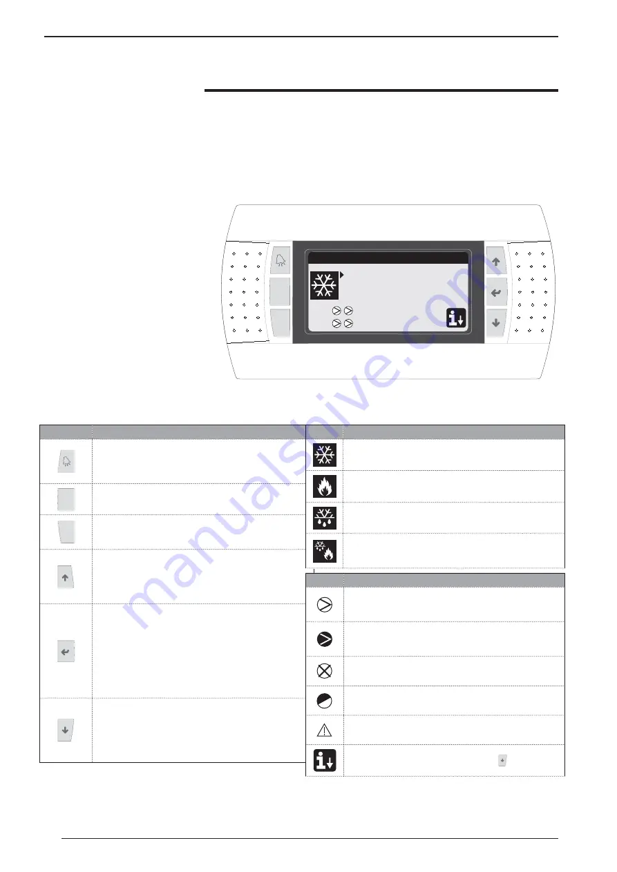
The unit control panel allows quick set-
ting of the machine functioning param-
eters and their display. The display is
made up from a graphical matrix with
132 x 64 pixel in order to signal the
type of functioning, displaying set pa-
rameters and any alarms that have in-
tervened. All default settings and any
modifi
cations are memorised in the
board. With installation of the PGD1
remote panel, it is possible to replicate
all functions and settings available from
Function
Key
ALARMS key
• One press displays the list of active alarms;
• One prolonged press (at least 5 seconds) resets the active
alarm;
Prg
MENU ACTIVATION key
• Pressing this key activates navigation among the menus;
Esc
MENU EXIT key
• Pressing this key goes back to the display of the previous
menu;
NAVIGATION key (+)
• Pressing this key while navigating among the menus/
parameters, allows to pass to the next menu/parameter;
• Pressing this key during modification of a parameter,
increases the value of the parameter selected;
NAVIGATION key (enter)
• Pressing this key while navigating among the menus, allows
to enter the menu selected;
• Pressing this key during navigation among parameters,
allows to select the parameter displayed and enter the modi-
fication mode;
• Pressing this key during modification of a parameter,
confirms the modifications to the value of the parameter
selected;
NAVIGATION key (-)
• Pressing this key while navigating among the menus/
parameters, allows to pass to the previous menu/param-
eter;
• Pressing this key during modification of a parameter,
decreases the value of the parameter selected;
Icon
Meaning
Cooling mode activated
Heating mode activated
Simultaneous defrosting mode activated
Separate defrosting mode activated. This mode is only avail-
able for twin-circuit models, in which it is possible to proceed
with defrosting engaging just one circuit;
Icon
Meaning
• FIXED icon = Compressor OFF;
• FLASHING icon = Compressor in switch-on phase, in stand-
by due to safety times;
• FIXED icon = Compressor ON;
• FLASHING icon = Compressor in switch-off phase, in stand-
by due to safety times;
Compressor forded off;
Limited compressor;
Compressor in alarm conditions;
Access to the “quick menu” by pressing the key
The user interface is represented by a
graphical display with six keys for navi-
gation. The displays are organised via a
hierarchy of menus, which can be acti-
vated by pressing the navigation keys.
The display default of these menus is
represented by the main menu. Navi-
gation among the various parameters
takes place using the arrow keys po-
sitioned on the right side of the panel.
These keys are also used to modify the
selected parameters.
• INTERFACE COMMAND KEYS:
• MAIN MENU ICONS:
o


