AERMEC NRL2000A Technical Manual Download Page 9

9

Aermec cod. 14.09 4086982_03

NRL 2000-3600 60Hz

EN

5. 

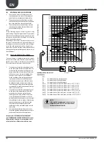
DESCRIPTION OF COMPONENTS

5.1. 

CHILLER CIRCUIT

SCROLL COMPRESSORS 

High efficiency scroll-type hermetic compressors, as-
sembled on elastic antivibration supports, driven by a 
2-pole electric motor with internal thermal protection. 
of the electric heater casing included as standard. The 
heater is automatically powered when the unit stops, 
provided that the unit is kept under tension.

WATER SIDE HEAT EXCHANGER

Of the plate-type (AISI 316), externally insulated with 
closed cell material to reduce thermal dispersion. 
Fitted, as standard, with antifreeze heater.

5.1.1. 

WATER FEATURES

SOURCE SIDE HEAT EXCHANGER

Made with copper pipes and aluminium louvered  fins 
blocked by mechanical expansion of the pipes. Provi-
ded with protective grid.

DESUPERHEATER / TOTAL RECOVERY 

Unit with (AISI 316) heat plate, insulated externally 
with closed cell material to reduce heat loss.

CYCLE INVERSION VALVE

(ONLY HEAT PUMP VERSION)

4way cycle inversion valve. Inverts the flow of refrige-
rant gas.

LIQUID STORAGE TANK

(ONLY HEAT PUMP VERSION/TOTAL RECOVERY)

Compensates the difference in volume between louve-
res coil and plate exchanger, withholding excess liquid.

DEHYDRATOR FILTER

Hermetic-mechanical with cartridges made of ceramic 
and hygroscopic material, able to withhold impurities 
and any traces of humidity present in the cooling 
circuit.

ONE-WAY VALVES

Allows the passage of the refrigerant in just one 
direction.

MECHANICAL THERMOSTATIC VALVE

The mechanical valve, with external equaliser positio-
ned at the evaporator inlet, modulates the flow of gas 
to the evaporator, according to the heat load, in order 
to ensure a correct heating level of the intake gas.

SOLENOID VALVE

The valve closes when the compressor turns off, 
preventing the flow of refrigerant gas towards the 

evaporator.

INDICATOR FOR LIQUID PASSAGE WITH HUMIDITY 
PRESENCE SIGNAL

Used to check the refrigerant gas load and the eventual 
presence of humidity in the cooling circuit.

LIQUID AND PRESSING LINE TAPS

(ONLY COOLING VERSION)

Allows interruption of the refrigerant in the case of 
extraordinary maintenance

.

LIQUID SEPARATOR

(ONLY HEAT PUMP VERSION)

Located on the suction point of the compressor, to pro-
tect against any flowback of liquid refrigerant, flooded 
start-ups, operation in the presence of liquid.

BY PASS SOLENOIDE VALVE

(ONLY HEATING RECOVERY VERSION)

By-passes the thermostatic valve during the defrosting 
cycle.

5.2. 

FRAME AND FANS

SUPPORT FRAME

Load-bearing structure Made of hot-galvanised steel 
sheet of a suitable thickness, varnished with polyester
powders able to resist atmospheric agents over time.

VENTILATION UNIT

Axial fan, balanced statically and dynamically. The elec-
tric fans are protected electrically by magnet-circuit 
breakers and mechanically by anti-intrusion metal 
grids, according to the IEC EN 60335-2-40 Standard.

5.3. 

HYDRAULIC CIRCUIT STANDARD COM

-

PONENTS

FLOW SWITCH

It checks that there is circulation of water.If
this is not the case, it blocks the unit

WATER TEMPERATURE  PROBE (IN-OUT)

AIR VENT

Of the automatic type, assembled on the upper part of 
the hydraulic system; it releases any air bubbles that 
may be present in the system.

DRAIN TAP

5.4. 

HYDRAULIC COMPONENTS FOR CONFI

-

GURABLE VERSIONS

CIRCULATION PUMP

(HIGH/LOW PUMP)

Depending on the characteristics of the pump chosen, 
it offers a useful head to overcome the pressure drops 
in the system.

EXPANSION TANK

(STANDARD SUPPLY TO PUMP AND STORAGE TANK 

VERSION)

With nitrogen pre-load membrane.

SAFETY VALVE

Equipped with a piped discharger and intervenes by 
discharges the over pressure in case of anomalous 
pressures.

STORAGE TANK

In order to reduce the thermal dispersion and elimina-
te the phenomenon of the formation of condensation, 
it is insulated with polyurethane material of a suitable 
thickness. It is required to reduce the number of peaks 
of the compressor and to even the temperature of 
water to be sent to the utilities. 

STORAGE TANK DRAIN TAP 

WATER FILTER

Equipped with steel filtering mesh; prevents the heat 
exchangers from clogging.

5.5. 

SAFETY AND CONTROL COMPONENTS

HIGH PRESSURE SWITCH (MANUAL RESET)

With fixed calibration, placed on high pressure side of 
cooling circuit, inhibits functioning of compressor if
abnormal work pressure occurs.

HIGH PRESSURE TRANSDUCER

Placed on high pressure side of cooling circuit, signals 
the work pressure to control board, generating a pre-
warning in case abnormal pressure occurs.

LOW PRESSURE TRANSDUCER

Allows displaying, on the microprocessor board display, 
the value of the compressor's suction pressure (one 
per circuit) on the low-pressure side of the cooling  
circuit

SAFETY VALVE

Equipped with a piped discharger and intervenes by 
discharges the over pressure in case of anomalous 
pressures.
- Set at 45 bar on the branch HP
- Set at 30 bar on the branch LP

LOW PRESSURE SWITCH

5.6. 

ELECTRICAL PANEL CONTROL AND 
POWER

Electric board in compliance with standards EN 60204-
1/IEC 204-1, complete with:

-   door lock main isolating switch,
-   fuses and contactors for compressors and fans,
-   terminals for REMOTE PANEL,
-   spring type control circuit terminal board,
-   outdoor electric board with double door and 

gaskets,

PH

6-8

Electric 
conductivity

less than 200 mV/cm 
(77°F / 25°C)

Chloride ions

less than 50 ppm

Sulphuric acid ions

less than 50 ppm

Total iron

less than 0.3 ppm

Alkalinity M

less than 50 ppm

Total hardness

less than 50 ppm

Sulphur ions

none

ammonia ions

none

Silicone ions

less than 30 ppm

Summary of Contents for NRL2000A

Page 1: ...INRLTY_14 09 4086982_03 EN 60Hz Technical manual NRL 200 360 CHILLER REVERSIBLE HEAT PUMP EXTERNAL UNIT HIGH EFFICIENCY HOT WATER PRODUCING UP TO 131 F 55 C POWER SUPPLY 60Hz 60Hz ...

Page 2: ...erience and special design studies and has been made of the highest grade materials and with cutting edge technology In addition all our products bear the EC mark indicating that they meet the requirements of the European Machine Directive regarding safety The standard of quality is permanently being monitored and AERMEC products are therefore a synonym for Safety Quality and Reliability The data ...

Page 3: ...E GRAPH 16 9 3 PROJECT DATA 16 9 4 INPUT POWER AND COOLING CAPACITY STANDARD VERSION HEAT PUMP IN COOLING MODE 17 10 CORRECTIVE FACTORS FOR WATER TEMPERATURES DIFFERENT THAN THE NOMINAL WATER TEMPERATURE 18 10 1 RESE E ASSORBIMENTI DIVERSI DAL NOMINALE 18 10 3 HEATING CAPACITY AND INPUT POWER 18 9 5 FOR ΔT DIFFERENT FROM THE RATED VALUE 18 10 2 FOULING FACTORS 18 11 PRESSURE DROPS 19 11 1 SYSTEM S...

Page 4: ...4 Aermec cod 14 09 4086982_03 NRL 2000 3600 60Hz EN ...

Page 5: ... to small commercial or residential buildings Maximum reliability The presence of several scroll compressors allows NRL chillers various partialisations of the cooling capacity Models 1 NRL standard chiller 2 NRL H heat pump 3 NRL C motocondensing The versions can be in different set ups at the same time in order to satisfy a wide range of plant enginee ring solutions 1 A HIGH EFFICIENCY 2 E SILEN...

Page 6: ...Total recovery 11 Version A High efficiency E High efficiency low noise data on the mand 12 Coils Alluminium R Copper S Copper tin plated V Epoxy coated 13 Fans Standard I Fan speed modulating for condensation control 14 Power supply 7 460V 10 3 60Hz with thermomagnetic switches 8 575V 10 3 60Hz with thermomagnetic switches 15 16 Hydronic kit 00 Without hydronic kit 01 Tank and single low head pum...

Page 7: ...UIT CN TEV IDL IDL HPT HPS LPT CP CP LPT BHE HPT HPS TEV F F CN KEY BHE PLATE HEAT EXCHANGER CN AIR SIDE EXSCHANGE CP COMPRESSOR F FILTER DRIER HPS HIGH PRESSURE SWITCH HPT HIGH PRESSURE TRANSDUCERS IDL LIQUID INDICATOR LPT LOW PRESSURE TRANSDUCER 4 1 NRL ONLY COOLING ...

Page 8: ...OMPRESSOR CV ONE WAY VALVES F FILTER DRIER HPS HIGH PRESSURE SWITCH HPT HIGH PRESSURE TRANSDUCERS IDL LIQUID INDICATOR LPT LOW PRESSURE TRANSDUCERS LS LIQUID SEPARATOR VIC REVERSE CYCLE VALVE 4 2 COOLING CIRQUIT NRL HEAT PUMP HPT HPS LS VIC VIC LS HPS LPT LPT HPT BHE IDL IDL CP CN CV CV CV CV CV CN TEV TEV F AL F CV CV AL CP CV ...

Page 9: ...time VENTILATION UNIT Axial fan balanced statically and dynamically The elec tric fans are protected electrically by magnet circuit breakers and mechanically by anti intrusion metal grids according to the IEC EN 60335 2 40 Standard 5 3 HYDRAULIC CIRCUIT STANDARD COM PONENTS FLOW SWITCH It checks that there is circulation of water If this is not the case it blocks the unit WATER TEMPERATURE PROBE I...

Page 10: ... consumption Condensation check based on the pressure rather than on temperature for absolute stability with DCPX revs adjuster accessory Inverse condensation check for the heat pump functioning mode also in summer with DCPX revs adjuster accessory Pre alarms with automatic reset in the case of alarm a certain number of restarts are allowed before the definitive block Alarm on the ΔT to identify w...

Page 11: ...in a system in which several units are installed in parallel always ensuring a constant delivery to the evaporators PGS Daily Weekly Programmer Allows you to programme two time bands per day two switch on off cycles and to have differentiated programming for each day of the week PRM1 PRM2 FACTORY FITTED ACCESSORY It is a manual pressure switch electrically wired in series with the existing automat...

Page 12: ...ater Alls nr W 4 150 4 150 4 150 4 150 4 150 4 150 4 150 Water content Alls l 24 24 28 24 28 28 32 32 35 35 39 39 43 43 Water connections Alls inch 3 3 3 3 3 3 3 COMPRESSORS SCROLL Number circuit n n 8 4 8 4 8 4 8 4 8 4 10 4 12 4 HEAT EXCHANGER SYSTEM SIDE Exchanger capacity gal 2 x 7 0 7 0 8 0 2 x 8 0 2 x 8 7 2 x 8 7 2 x 8 7 2 x 8 7 hydraulic connections victaulic Ø 3 3 4 4 4 4 4 4 HYDRONIC KIT S...

Page 13: ...92 47 494 13 549 33 596 73 655 19 670 38 695 02 M C A 460V A 298 60 362 57 425 47 482 06 532 32 571 11 601 56 575V A 243 24 299 56 354 75 419 43 477 89 493 08 500 45 M O P 460V A 298 60 362 57 425 47 482 06 532 32 571 11 601 56 575V A 267 85 334 31 389 50 468 79 527 25 542 44 535 19 RECOM FUSE 460V A 300 400 450 500 500 600 600 575V A 250 300 350 450 500 500 500 MODELS WITH HIGH PRESSURE PUMP L R ...

Page 14: ...V A 220 0 256 3 292 6 310 1 328 5 382 0 435 8 Total input current heating mode 460V A 286 5 318 0 349 4 393 6 428 8 514 8 552 7 575V A 229 2 254 4 279 6 315 0 343 2 433 9 461 1 COMPRESSORS SCROLL Number circuit n n 8 4 8 4 8 4 8 4 8 4 10 4 12 4 EXCHANGER SYSTEM SIDE Exchanger capacity gal 2 x 7 0 7 0 8 7 2 x 8 7 2 x 8 7 2 x 9 9 2 x 9 9 2 x 9 9 hydraulic connections victaulic Ø 3 3 4 4 4 4 4 4 HYDR...

Page 15: ...589 76 645 06 723 95 774 21 813 00 821 15 575V A 405 75 500 77 549 33 596 73 655 19 670 38 695 02 M C A 460V A 313 80 370 17 425 47 482 06 532 32 571 11 601 56 575V A 256 52 306 20 354 75 419 43 477 89 493 08 500 45 M O P 460V A 344 25 412 09 467 39 536 55 586 81 625 60 643 48 575V A 281 13 340 95 389 50 468 79 527 25 542 44 535 19 RECOM FUSE 460V A 300 400 450 500 500 600 600 575V A 250 300 350 4...

Page 16: ...ATTENTION Contact our technical sales department if the unit needs to operated outside the operating limits ATTENTION If the unit is installed in particu larly windy areas we recommend providing for windbreak to avoid malfunctioning of the DCPX_UL device 25 20 15 30 35 40 45 50 55 60 10 15 20 5 0 5 10 15 20 25 30 35 40 45 50 C C F F 14 5 4 23 32 41 50 59 59 68 68 77 77 86 86 95 95 104 104 113 113 ...

Page 17: ...city efficiency and electrical input power in conditions differing from normal conditions are obtained by multiplying the nominal values Pf Pa by the respective corrective co efficients Cf Ca The following diagrams show how to obtain corrective co efficients to use for units in their various versions in cooling mode external air temperature to which reference is made is shown in correspondence to ...

Page 18: ...ffering from normal conditions are obtained by multiplying the nomi nal values Pt Pa by the respective coefficient correctives Ct Ca The following diagram shows how to obtain cor rective coefficients the produced hot water tem perature to which reference is made is shown in correspondence to each curve assuming a water temperature difference equal to 5 C between the condenser inlet and outlet The ...

Page 19: ...factor Nominal value referring to Air temperature 35 C 95 F Water at the desuperheater 45 50 C 113 122 F t 5 C 41 F Units with Desuperheater D do not envision the following versions YD XD only for temperature under 4 C 39 2 F 45 C 40 C 35 C 30 C 25 C 0 00 35 40 45 50 55 60 65 0 50 1 00 1 50 2 00 2 50 3 00 20 C 68 F 95 100 105 110 115 120 125 130 135 140 145 149 113 F 104 F 95 F 86 F 77 F Temperatu...

Page 20: ... temperature under 4 C 39 2 F 35 C 95 F 40 C 104 F 45 C 113 F 50 C 122 F 55 C 131 F 5 0 9 1 0 1 1 1 2 1 3 1 4 1 5 6 7 8 9 10 11 12 13 14 15 16 17 18 C 64 4 F 41 41 43 45 47 49 51 53 55 57 59 61 63 Temperature of the water produced RECOVERED HEATING CAPACITY CORRECTIVE CO EFFICIENTS Cr 35 C 95 F 40 C 104 F 45 C 113 F 50 C 122 F 55 C 131 F 5 0 7 0 8 0 9 1 0 1 1 1 2 6 7 8 9 10 11 12 13 14 15 16 17 18...

Page 21: ...15 68 20 86 30 104 40 122 50 Coefficients 1 02 1 0 98 0 97 0 95 0 93 0 91 Inlet water temperature 104 F 40 C Water product temperature 113 F 45 C External air temperature 45_43 F 7_6 C Average water temperature For temperatures other than 50 F 10 C to use the table of correction factors Average water temperature F C 73 4 23 82 4 28 91 4 33 100 4 38 109 4 43 118 4 48 127 4 53 136 4 58 Coefficients ...

Page 22: ... 14 50 21 75 29 00 36 25 43 51 50 76 58 01 20000 70000 120000 N R L 2 2 5 0 2 5 0 0 NRL 3300 3600 N R L 2 8 0 0 3 0 0 0 N R L 2 0 0 0 170000 220000 ti ti l h g m 88 308 528 748 969 ti ti 0 50 100 150 200 250 300 350 400 0 7 25 14 50 21 75 29 00 36 25 43 51 50 76 58 01 ti ti 20000 70000 120000 170000 220000 l h 88 308 528 7 48 969 g m ti N R L 3 0 0 0 2 8 0 0 N R L 2 5 0 0 N R L 2 2 5 0 N R L 2 0 0...

Page 23: ... 60000 80000 100000 120000 140000 160000 180000 200000 88 176 352 440 616 704 792 880 308 528 l h g m ti ti NRL 3600 3300 N R L 2 8 0 0 3 0 0 0 N R L 2 5 0 0 N R L 2 2 5 0 N R L 2 0 0 0 0 0 20000 40000 60000 80000 100000 120000 140000 160000 180000 200000 88 176 352 440 616 704 792 880 308 528 l h g m ti ti 50 100 150 200 250 7 25 14 50 21 75 29 00 36 25 NRL 3600 3300 N R L 2 8 0 0 3 0 0 0 N R L 2...

Page 24: ...ecommended to produce desired water tempe rature is on the lower axis 2 If you wish to calculate the percentage of glycol on the basis of the temperature of the water produced enter from the right axis and on reaching the curve draw a vertical line which in turn will intercept all the other curves the points obtained from the upper curves represent the coefficients for the correction of the coolin...

Page 25: ...est user does not exceed a level difference of 55 metres 2 Check that the lowest user can sustain the global pressure acting at that point H max 1 180 44 ft 55 m H 40 19 ft 12 25 m H H 0 ft 0 m Ptar H 10 2 0 3 Ptar 21 75 psi 1 5 bar Ptar 21 75 psi 1 5 bar H min 2 17 MINIMUM WATER CONTENT NRL 2000 2250 2500 2800 3000 3300 3600 Number of compressor circuits n n 8 4 8 4 8 4 8 4 8 4 10 4 12 4 Minimum ...

Page 26: ...2500 11 21 32 44 57 71 85 100 NRL 2800 11 25 33 49 68 75 89 100 NRL 3000 12 25 37 49 62 75 87 100 NRL 3300 11 22 32 43 52 62 71 81 90 100 NRL 3600 6 12 19 26 33 41 50 59 69 79 89 100 Power steps HEATING CAPACITY 1º 2º 3º 4º 5º 6º 7º 8º 9º 10º 11º 12º NRL 2000 12 25 37 49 62 75 87 100 NRL 2250 11 25 33 49 68 75 89 100 NRL 2500 12 25 37 49 62 75 87 100 NRL 2800 11 22 32 43 52 62 71 81 90 100 NRL 300...

Page 27: ... 72 4 3600E 93 61 73 84 9 82 4 84 8 88 0 88 2 81 0 72 9 2000HA 96 64 76 88 9 85 4 88 6 89 9 87 3 83 1 72 9 2250HA 96 64 76 88 6 88 8 89 2 90 4 88 1 82 6 71 1 2500HA 97 65 77 89 1 90 9 90 3 91 5 89 4 83 0 70 1 2800HA 98 66 78 91 9 88 4 89 8 94 0 87 2 79 0 69 9 3000HA 99 67 79 93 9 88 4 90 8 93 0 88 2 80 5 71 9 3300HA 99 67 79 91 9 90 9 92 3 94 0 89 2 81 0 71 9 3600HA 99 67 79 90 9 91 4 92 3 94 5 88...

Page 28: ...0 435 30 435 30 435 30 435 30 435 30 FAN THERMOMAGNETIC SWITCHES Fan MTV q ty 8 8 10 10 12 12 12 12 12 12 16 16 16 16 MTV 460V 3 60Hz A 4 2 4 2 4 2 4 2 4 2 4 2 4 2 MTV 575V 3 60Hz A 3 7 3 7 3 7 3 7 3 7 3 7 3 7 460V VERSIONI A E A n x A 8 x 4 2 12 x 4 2 16 x 4 2 16 x 4 2 16 x 4 2 16 x 4 2 16 x 4 2 VERSIONI HA HE A n x A 12 x 4 2 14 x 4 2 16 x 4 2 16 x 4 2 16 x 4 2 16 x 4 2 16 x 4 2 575V VERSIONI A ...

Page 29: ...L 2800 460 V LOW PUMP CP1 CP3 CP1A CP3A 51 5 A 7 2 A 16 x 4 2 A SF 16 x 4 2 A PC HIGH PUMP CP2 CP4 CP2A CP4A CP2B CP4B 40 5 A 13 2 A 575 V LOW PUMP CP1 CP3 CP1A CP3A 41 7 5 8 A 16 x 3 7 A SF 16 x 3 7 A PC HIGH PUMP CP2 CP4 CP2A CP4A CP2B CP4B 32 3 A 10 6 A NRL 3000 460V LOW PUMP CP1 CP3 CP1A CP3A CP1B CP3B 40 5 A 7 2 A 16 x 4 2 A SF 16 x 4 2 A PC HIGH PUMP CP2 CP4 CP2A CP4A CP2B CP4B 40 5 A 13 2 A...

Page 30: ...e not binding Aermec reserves the right to make all the modifications considered necessary for improving the product at any time AERMEC S p A 37040 Bevilacqua VR Italia Via Roma 996 Tel 39 0442 633111 Telefax 39 0442 93577 www aermec com sales aermec com ...

Reviews: