17
Aermec cod. 14.09 4086982_03
NRL 2000-3600 60Hz
EN
Outside
air t
empe
ra
tur
e
b.s. b.s. °C/ °F
Outside
air t
empe
ra
tur
e
b.s. °C/ °F
C
ORRE
C
TION
C
OEFFICIEN
T
S (Ca)
C
ORRE
C
TION
C
OEF
FICIENT
S
(Cf
)
0,6
0,7
0,8
0,9
1
1,1
1,2
1,3
1,4
-4
-6
-2
0
2
4
6
8
10
12
14
16
18
40°C /
104°F
45°C /
113 °F
46°C /
114.8 °F
35°C
/ 95°F
30°C /
86°F
25°C
/ 77°F
20°C
/ 68°F
39.2
21.2
28.4
32.0
35.6
39.2
42.8
46.4
50
53.6
57.2
60.8
64.4
°C
°F
0,4
0,5
0,6
0,7
0,8
0,9
1
1,1
1,2
1,3
1,4
1,5
1,6
-6
-4
-2
0
2
4
6
8
10
12
14
16
18
39.2
21.2
28.4
32.0
35.6
39.2
42.8
46.4
50
53.6
57.2
60.8
64.4
°C
20°C / 68°F
25°C / 77°F
30°C / 86°F
35°C / 95°F
40°C 104°F
45°C 113 °F
46°C 114.8 °F
°F
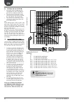
9.4.
INPUT POWER AND COOLING CAPACITY
"STANDARD VERSION"/ "HEAT PUMP VER
-
SION IN COOLING MODE"
The cooling capacity efficiency and electrical input power
in conditions differing from normal conditions are obtained
by multiplying the nominal values (Pf, Pa) by the respective
corrective co-efficients (Cf, Ca).
The following diagrams show how to obtain corrective co-
efficients to use for units in their various versions in cooling
mode; external air temperature, to which reference is made,
is shown in correspondence to each curve.
KEY:
Cf:
Corrective coefficient of the
cooling capacity.
Ca:
Corrective coefficient of the
input power.
INPUT POWER IN COOLING MODE CORRECTIVE COEFFICIENTS
COOLING CAPACITY CORRECTIVE COEFFICIENTS
WATER PRODUCTED
WATER PRODUCTED
FOR ∆t DIFFERENT TO THE NOMINAL
FROM 10.01°F / 5.56°C.
For ∆t different from 10.01°F / 5.56°C at the evaporator
use Tab. 11.3.1. to obtain the correction factors of the
cooling capacity and input power. In order to consider
exchanger dirtying, use the relative dirtying factors
Tab.11.4.1.


