


18
Aermec cod. 14.09 4086982_03
NRL 2000-3600 60Hz
EN
10.
CORRECTIVE FACTORS FOR WATER TEMPERATURES DIFFERENT THAN THE NOMINAL WATER TEMPERATURE "°" VERSION
10.1. RESE E ASSORBIMENTI DIVERSI DAL NOMINALE
9.5. FOR Δt DIFFERENT FROM THE RATED VALUE
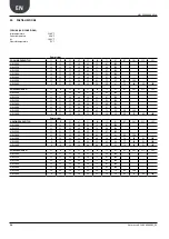
The performances given by the technical data refer
to AHRI standard conditions: flow rate 0.043l/s per
kW (Δt 10.01°F / 5.56°C).
Use table to obtain the corrective factors of the
cooling capacity and input power different than Δt
10.01°F / 5.56°C.
10.2. FOULING FACTORS
The performance levels given by the technical data
refer to conditions with clean tubes, with a fouling
factor = 1.
For other fouling factor values, multiply the data of
performance table by the coefficients given.
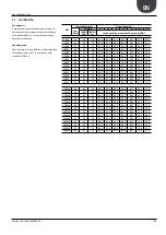
ΔT DIFFFERENT FROM THE RATED VALUE
(ΔT 5°C_10.01°F)
3°C/5,40°F 5,56°C/10,01°F
8°C/14,40°F
10°C/18°F
Cooling capacity correction factors
0,99
1
1,02
1,03
Input power correction factors
0,99
1
1,01
1,02
FOULING FACTOR [K*M2]/[KW] [K*m2]/[W]
0,00005
0,0001
0,0002
Cooling capacity correction factors
1
0,98
0,94
Input power correction factors
1
0,98
0,95
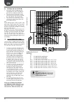
10.3. HEATING CAPACITY AND INPUT
POWER
−
"HEAT PUMP VERSIONS"
The heating capacity efficiency and electrical
input power in conditions differing from normal
conditions are obtained by multiplying the nomi-
nal values (Pt, Pa) by the respective coefficient
correctives (Ct, Ca).
The following diagram shows how to obtain cor-
rective coefficients; the produced hot water tem-
perature, to which reference is made, is shown in
correspondence to each curve, assuming a water
temperature difference equal to 5°C between the
condenser inlet and outlet.
The yields are intended net of de-frosting cycles.
KEY:
Ca:
Corrective co-efficient of the
input power.
Ct:
Corrective co-efficient of the
heating capacity.
FOR ∆t DIFFERENT TO THE NOMINAL
FROM 10.01°F / 5.56°C.
For ∆t different from 10.01°F / 5.56°C at the evaporator
use Tab. 11.3.1. to obtain the correction factors of the
cooling capacity and input power. In order to consider
exchanger dirtying, use the relative dirtying factors
Tab.11.4.1.
Ca c
ooling mode
-15
-12
-9
-6
-3
0
3
6
9
12
15
18
21
24
27
30
°C
5
10
-15,8
21,2
26,6
32
37,4
42,8
48,2
53,6
59
64,4
69,8
75,2
80,6
86
°F
7
44,6
77
86
95
104
113
131
°F
122
0.5
0.6
0.7
0.8
0.9
1.1
1.2
1.3
1.0
25
30
35
40
45
55
°C
50
Ct
0.5
0.6
0.7
0.8
0.9
1.1
1.2
1.3
1.4
-15
-12
-9
-6
-3
0
3
6
9
12
25
°C
°F
30
35
40
45
55
50
77
86
95
104
113
131
122
15
18
21
24
27
30
°C
5
10
-15,8
21,2
26,6
32
37,4
42,8
48,2
53,6
59
64,4
69,8
75,2
80,6
86
°F
1.0
7
44,6
External air temperature (°C)
INPUT POWER IN HEATING MODE CORRECTIVE CO-EFFICIENTS
HEATING CAPACITY CORRECTIVE CO-EFFICIENTS


