background image

12


Simple Logger

®

 II Model L261

4.2 

Connecting the Simple Logger

®

 II to a Computer


INSTALL THE DATAVIEW

®

 SOFTWARE BEFORE CONNECTING THE SIMPLE 

LOGGER

®

 II TO THE COMPUTER.

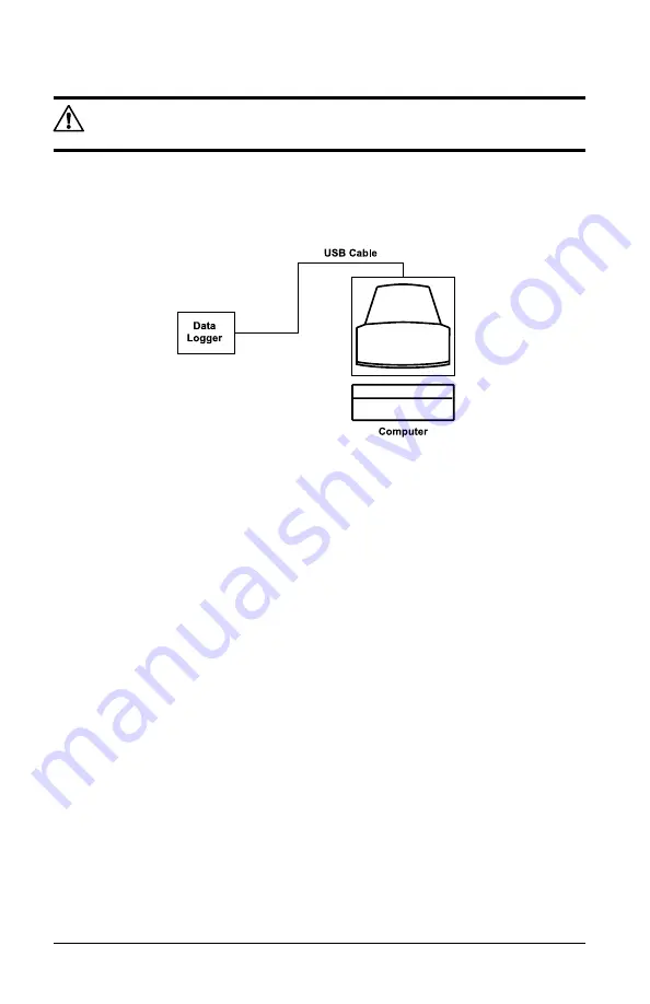
Figure 4-1 shows a typical hook-up. The Simple Logger

®

 II utilizes an opti-

cally isolated USB communication port.

Refer to the computer manual to locate the USB port on your computer.

Figure 4-1

The logger can be connected to the computer during a recording session, 
however, additional battery drainage will occur to support the active USB 
connection.

4.3 

Turning the Unit On

Turn the instrument ON by performing one of the following:

•  Press  and  hold  the 

PRESS

  button  for  approximately  2  seconds. 

Release the button after all five LEDs light up in unison. The unit is 

now in the STANDBY mode (Green LED single-blinks). 


NOTE: 

if the LEDs light in sequence the instrument is already ON.  In 

this case continue to hold the 

PRESS

 button until all LEDs are OFF.

•  Connect the instrument to a USB port on your computer and establish 

communication  with  the  instrument  using  DataView

®

. The  logger  will 

remain ON while a communication link with DataView

®

 is active (pro-

vided sufficient battery power is available during the communication 

session).

Summary of Contents for Simple Logger II

Page 1: ...E N G L I S H User Manual SIMPLE LOGGER II TRMS VOLTAGE MODEL L261...

Page 2: ...ease record this number and purchase date for your records SIMPLE LOGGER II MODEL _______________________________________________ SERIAL _______________________________________________ PURCHASE DATE _...

Page 3: ...3 4 Safety 9 4 OPERATION 10 4 1 LED Control Operation and Status Function 10 4 2 Connecting the Simple Logger II to a Computer 12 4 3 Turning the Unit On 12 4 4 Recording Data 13 4 4 1 Starting a Rec...

Page 4: ...APPENDIX A TROUBLESHOOTING 21 APPENDIX B GLOSSARY 22 Repair and Calibration 23 Technical and Sales Assistance 23 Limited Warranty 24 Warranty Repairs 24...

Page 5: ...ument is protected by double or reinforced insulation Indicates aWARNING and that the operator must refer to the user manual for instructions before operating the instrument Failure to follow or carry...

Page 6: ...control units or meters 1 3 Receiving Your Shipment Upon receiving your shipment make sure that the contents are consistent with the packing list Notify your distributor of any missing items If the e...

Page 7: ...t times per second The measurement process is performed no more than eight times per second TRMS calculations are performed on a single line cycle This means that the input s are ignored between measu...

Page 8: ...tors The LEDs on the instrument serve two functions control operation and status function The control operation function when holding down the PRESS button is indicated with text to the left of each L...

Page 9: ...U and is located under the top cover To access this button remove the battery compartment cover remove the four screws holding the two halves of the case together The reset switch is the smaller switc...

Page 10: ...ted Power Source 2x1 5V AA cell alkaline batteries Battery Life 100 hours to 45 days dependent on sample rate and recording length This unique recording mode provides the opportunity to continuously r...

Page 11: ...ibration IEC 68 2 6 1 5mm 10 to 55Hz Shock IEC 68 2 27 30G Drop IEC 68 2 32 1m 3 3 Environmental Operating Temperature 14 to 122 F 10 to 50 C Storage Temperature 4 to 140 F 20 to 60 C Relative Humidit...

Page 12: ...oes OFF At this point releasing the button will result in no action being taken This provides a mechanism to cancel or ignore the button press Control of the instrument is performed by pressing and ho...

Page 13: ...utton for 0 5 seconds If the LED blinks it is not OFF Note Overload occurs when any input is 10 above its input range When the battery voltage goes below 1 7 volts the instrument will shut down termin...

Page 14: ...active USB connection 4 3 Turning the Unit On Turn the instrument ON by performing one of the following Press and hold the PRESS button for approximately 2 seconds Release the button after all five LE...

Page 15: ...needs see the Configuring the Simple Logger II section inside the DataView user manual Once a configuration is written to the instrument the logger will no longer need to be connected to DataView to...

Page 16: ...he Downloading Recorded Instrument Data section inside the DataView user manual that shipped with the instrument 4 6 Erasing Data from Memory Erasing data from the instrument s memory can only be perf...

Page 17: ...al operations on a single or multiple input or other channels Sample Rate The rate at which the instrument measures inputs Storage Rate The rate at which channel measurements are stored 4 7 1 Trend Me...

Page 18: ...Start Stop The PRESS button is pushed until the STOP ORANGE LED lights up and is released before the next LED lights The Stop Recording command from the Simple Logger II Control Panel is sent to the u...

Page 19: ...D will turn OFF The logger continues to record until the battery voltage drops below 1 7V Pressing the PRESS button may not turn the unit ON at all The battery voltage may rise slightly after the unit...

Page 20: ...top cover To access this button remove the battery compartment cover remove the four screws holding the two halves of the case together The reset switch is the smaller switch located on the exposed P...

Page 21: ...will be lost Event Pressing the RESET Button when a Recording has Ended The GREEN LED single blinks The unit indicates that the memory is full double blinking RED Event The Logger is Waiting for a Ne...

Page 22: ...ies then replace cover Press the PRESS button for 2 seconds to turn ON NOTE It is recommended to store the unit with the batteries in it to preserve the internal clock If the instrument is stored with...

Page 23: ...next LED lights Make sure the RED LED is not double blinking If it is memory is full and you need to erase the data see 4 6 Make sure the Simple Logger II is properly configured so that you have Stor...

Page 24: ...om the logger to the computer Hz Hertz a unit of measure of frequency equivalent to cycles per second I O Input output a device or port capable of sending or receiving digital information Port A name...

Page 25: ...des calibration certificate plus recorded calibration data Ship To Chauvin Arnoux Inc d b a AEMC Instruments 15 Faraday Drive Dover NH 03820 USA Phone 800 945 2362 Ext 360 603 749 6434 Ext 360 Fax 603...

Page 26: ...ay return the instrument to us for repair provided we have your warranty registration information on file or a proof of purchase AEMC Instruments will at its option repair or replace the faulty materi...

Page 27: ......

Page 28: ...05 07 99 MAN 100311 v1 Chauvin Arnoux Inc d b a AEMC Instruments 15 Faraday Drive Dover NH 03820 USA Phone 603 749 6434 Fax 603 742 2346 www aemc com...

Reviews: