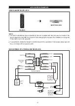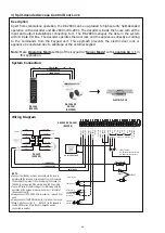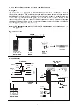
APPLICATION EXPANSIONS
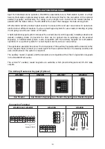
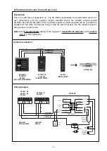
Apart from standard-alone operation, DK-2890 is expandable to be a Multi-station System or a High
Security Multi-station Split-decoded System with its Data I/O Bus for the connection of the optional
auxiliary keypad(s) and decoder. The wiring is very simple. Just connect all the related devices in
parallel with the Data I/O Bus. The DK-2890 is the server that manages the data among them.
A Multi-station System provides higher security in access control and user convenience to operate an
electric lock at different locations. Such as a dual keypad system for area needs controlling of going
in and going out with user codes or EM cards.
A Split-decoded keypad system increases the overall security with keypad(s) installing outside and
decoder installing inside. It prevents the door can be opened due to sabotage at the external
keypad(s). A Split-decoded system is also compatible with the auxiliary keypads for multi-station
operation. It is a perfect system for overall higher security and user convenience.
The application examples here show the connections of the auxiliary keypads and the decoder to the
server keypad. Please contact your local agent for these optional devices if increasing security and
user convenience to the system is required.
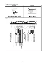
The auxiliary reader / keypads and the decoders are compatible with all the 2nd generation keypads
in the DK-2800 MK-II series.
The version"A" auxiliary reader keypads are available, which provide Wiegand and RS-232 data
outputs.
6
5
4
3
2
1
LED
DATA
I/O
TAMPER
N.C.
( + ) ( – )
12-24V DC
10
9
8
7
6
5
4
3
2
1
LED
DATA
I/O
TAMPER
N.C.
( + ) ( – )
12-24V DC
WIEGAND
D0
D1
BUZ
RS
232
Version"A" ONLY
Connection Terminal
AR-2809
AR-2806
AR-2802 and AR-2807
10
9
8
7
WIEGAND
D0
D1
BUZ
RS
232
Version"A"
ONL
Y
Aux. Reader-Keypad
Aux. Reader-Keypad
Aux. Reader-Keypad
Aux. Reader
AR-2809
AR-2807
AR-2806
AR-2802
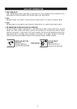
The Axiliary Readers & Keypad (Optional)
8 : GND (-) (Common Ground)
A common grounding point of the keypad, it is common to the Black wire, terminal 6.
9 : DATA I/O (Data Input/Output Port for Split-Decoded Operation)
A data bus for signal communication with the optional Access Controller in Split-decoded operation and
Auxiliary Reader-keypad in multi-station operation.
10 - 11 - 12 : OUTPUT 1 (Output Relay 1)
2 Amp relay dry contact controlled by the Group 1 user PINs or Cards for Output 1, recommended for door
strike. Terminal 10 is Normally Closed (N.C.), terminal 12 is Normally Open (N.O.) and terminal 11 is the
common point of the two contacts. Use N.C. output for Fail-safe locking device; and N.O. output for
Fail-secure locking device. The relay is programmable for Start/Stop (toggle) mode or Momentary timing
mode. See programming Location 51 for the details.
THE ON-BOARD LED INDICATORS
MAINS (AMBER)
------
I
t flashes in Standby. It shows the system status in synchronization with
........................................
the beep tones. The standby flashing can be set to OFF in programming.
........................................
See Location 73 for the details.
INHIBIT (RED)
-----
It is a system inhibited indicator. It lights up while the output 1 is locked-up.
DOOR (GREEN)
-----
It lights up for Output 1 activation.
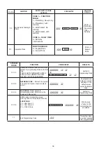
PACIFIER TONES & THE LED SIGNALS
The buzzer and the amber LED indicator give following tones and signals respectively for system status:
NOTE:
*
* *
* * *
STATUS
TONES *
AMBER LED
1) In Programming Mode
-----
ON
2) Successful Key Entry
1 Beep
1 Flash
3) Successful Code / Card Entry
2 Beeps
2 Flashes
4) Unsuccessful Code / Card Entry
5 Beeps
5 Flashes
5) Power Up Delay
Continuous Beeps
Continuous Flashes
6) Output Relay Activation **
1 Second Long Beep
7) In Standby ***
-----
1 Flash in 1 Second Interval
8) System Refreshing
Card or Code Already Stored in
-----
Fast Flashes for 2.5 Minutes
-----
Continuous 1 Beep/5 secs
11) Real -time-clock stopped after
power failure
10) Keypad link-up with Decoder Failed
)
9
System
1 Long Beep
-----
-----
-----
Continuous 3 Fast Beeps
/5 secs
All Pacifier Tones can be ON or OFF through the programming option at Location 71
The Output Relay Activation beep can be selected through the programming option at
Location 72
The Standby flashing can be ON or OFF through the programming option at Location 73
Summary of Contents for DK-2890
Page 2: ......
Page 48: ...AEI PROTECT ON SYSTEMS LIMITED www apo hk com...

