background image

29

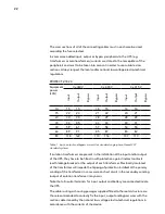
corresponding circuit breaker should trigger without affecting the supply of the 
remaining outlets (selective).

4.3.3. UPs coNNEctioN to Each battEry Pack iN  
cabiNEt, tErmiNals (X11, X12, X23 aNd X47, X48, X49)

as this is a device with class I protection against electric shocks, it is essential 
to install a protective earth conductor (connect earth (

)). Connect the 

conductor to the terminal 

(X5)

, before connecting the power supply to the 

UPs input.

IMPOrTanT FOr YOUr saFeTY: Do not turn the battery fuse holder switch or 
switch 

(Q3)

 located in the equipment or its equivalent 

(Q8)

 in the battery cabinet 

to “On” (Close), until the equipment prompts you during the startup procedure 
via the display, because it can cause irreversible damage to the equipment or  
accidents because the engineer is exposed to eleCTrICal DIsCHarGe  
DanGers. The UPs prompts before connection with the battery cabinet.

UPs connection with battery pack will be implemented with the supplied trunk 
cable by connecting one side to terminals 

(X11), (X23)

 and 

(X12)

 of the UPs and 

the other one to terminals 

(X47)

(X49)

 and 

(X48) 

on the battery pack. always 

respect the stated polarity in the labeling of each part and in this manual. The 
color of the cables (red for positive, black for negative, blue for middle tap (n)  
and green-yellow for earth bonding), see Fig. 20.

Turn off multiple battery packs in parallel. Firstly connect the black wire from the 
negative terminal of the UPs to the negative terminal of the first battery pack and 
then from there to the others. Proceed with the cables (positive: red, center tap: 
blue, protective earth, green-yellow) accordingly.

electrical discharge danger.

 If after starting up the UPs, it is required to 

disconnect the battery cabinet, the equipment has to be completely shutdown 
(see section 5.2). Turn off the battery fuse holder switch 

(Q8)

 located in the battery 

cabinet and/or fuse holder switch or switch 

(Q3)

 located in the UPs. Wait at least 

5 min. until the filter capacitors have been discharged.

Summary of Contents for Protect 2.33 2.0

Page 1: ...User Manual EN Protect 2 33 2 0 Uninterruptible Power Supply UPS ...

Page 2: ...orresponding legends for the equipment views 13 3 2 Structure 15 3 2 1 Structural schema 15 3 3 Operating principle 15 3 3 1 Normal operation 16 3 3 2 Operation with mains failure 16 3 3 3 Operation with inverter not active 16 3 3 4 Operation in manual bypass 17 3 4 Parallel operation 17 4 Installation 19 4 1 Important safety instructions 19 4 1 1 Battery safety instructions 20 4 1 2 Cabinet acces...

Page 3: ...S connection X36 33 5 Operation 35 5 1 Start up 35 5 1 1 Control before start up 35 5 1 2 Start up procedure 35 5 2 Complete UPS shutdown 37 5 3 Emergency power off EPO operation 38 5 4 Bypass manual switch Maintenance 38 5 4 1 Principle of operation 38 5 4 2 Transfer to maintenance bypass 38 5 4 3 Transfer to normal operation 39 6 Control panel and display description 41 6 1 Control panel parts 4...

Page 4: ...enu 4 0 56 6 3 6 DATA LOGGER level screen menu 5 0 69 7 Maintenance warranty and service 71 7 1 Basic maintenance guide 71 7 1 1 Battery fuses 71 7 1 2 Batteries 71 7 1 3 Cooling Fan 72 7 1 4 Capacitors 72 7 2 Warranty conditions 72 8 Annexes 73 8 1 General technical Specification 73 8 2 Safety Instructions 76 ...

Page 5: ...d here must be done by our staff or specifically authorised personnel According to our policy of constant evolution we reserve the right to modify the specifications in part or in whole without advance warning All reproduction or third party concession of this manual is prohibited without the previous written authorization of our firm 1 1 Using this manual The goal of this manual is to give explan...

Page 6: ...ble coming from the installation to this terminal Notes of information Additional topics that complement the basic procedures Preservation of the environment The presence of this symbol in the product or in its associated documentation states that when its useful life is expired it will not be disposed with the domestic refuse In order to avoid possible harm to the environment separate this produc...

Page 7: ...ser and installation manual information pertaining to safety instructions is provided These can be found in chapter 8 2 of this manual Before proceeding to installation or commissioning check that both sets of information are available Please refer to chapter 8 2 carefully Com pliance with safety instructions are available for you to understand and observe Once read keep the safety instructions av...

Page 8: ...ity and environmental officer The management designated person in charge of the quality and environment department who independent of other responsibilities has the responsibility and authority to assure that the processes of the quality and environmental management systems are established and maintained to inform the management about the operation of the quality and environmental management syste...

Page 9: ...ctromagnetic compatibility EMC EN IEC 62040 3 Uninterruptible power supply UPS Part 3 Methods of operation specification and test requirements The manufacturer s responsibility is excluded in the event of any modification or tampering with the product on the customer s side 2 3 Environmental protection This product has been designed to respect the environment and has been manufactured in accordanc...

Page 10: ...ews of the equipment 3 Presentation Fig 2 Cabinet front view for UPS up to 20 kVA with front door closed Fig 3 Cabinet front view for UPS from 30 to 80 kVA with front door closed CL CL PF PF PB PB RD RD RV RV RV fig 4 fig 4 ...

Page 11: ...g 6 Cabinet front view for UPS up to 20 kVA with front door opened 2 3 a b c d e 1 Fig 5 Communication connectors details Fig 7 Cabinet front view for UPS up to 30 to 80 kVA with front door opened Not available for Protect 2 33 2 0 ...

Page 12: ...abinet front view with front door closed Fig 9 No 1 3 battery cabinet front view with front door opened Fig 10 No 4 battery cabinet front view with front door closed Fig 11 No 4 battery cabinet front view with front door opened ...

Page 13: ...terminal S X3 Phase input terminal T X4 Neutral input terminal N X5 Main protection earthing terminal X6 Phase output terminal U X7 Phase output terminal V X8 Phase output terminal W X9 Neutral output terminal N X10 Earth bonding terminal for load or loads and or battery cabinet X11 Battery terminal X12 Battery terminal X23 Battery terminal N X31 DB9 connector COM RS232 and RS485 ports X32 DB9 con...

Page 14: ...LED red e General alarm In case of any alarm of the unit LED red Other abbreviations BL Mechanical block for manual bypass switch Q5 CL Lock for cabinet front door PB Levelers and immobilizing elements PC Control panel PF Cabinet front door PR Cable routing or wire cones RD Scroll wheel RV Ventilation grille SL Slot for optional intelligent card TB Terminal cover TS Slot cover SL t1 Screws fixing ...

Page 15: ...e conversion system AC DC DC AC with a sine wave output that gives safe protection in extreme conditions of power supply variations in voltage frequency electrical noises blackout and other power disturbances etc Whatever the kind of load that has to be protected these devices are prepared to assure quality and continuity in the electrical supply The operation is basically as follows Rectifier an ...

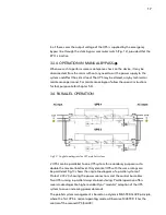
Page 16: ...ve alternating output stabilized in voltage and frequency to supply the loads connected to the output Fig 12 3 3 2 Operation with mains failure In the event of mains failure or power disturbance occur the group of batteries supplies the power needed to supply the inverter The inverter continues working normally independent of the lack of mains and the back up time of the device depends only on the...

Page 17: ... 3 4 Parallel operation 2 UPS s can be paralleled to one UPS system for redundancy purposes or to double the maximal load level Only identical UPS with the same ratings can be paralleled Fig 13 shows the single line diagram of a parallel system of Protect 2 33 2 0 showing the power connections and the control bus cables Two UPS running in parallel always do load sharing Parallel operation offers s...

Page 18: ... recover the redun dancy condition In case of more than 50 load per UPS the system will gener ate an alarm In case one UPS fails at more than 50 load per UPS the second UPS will take over and will run into overload It will supply the load according to the UPS overload capability After that condition both UPS will switch to bypass Parallel system for power enhancement Paralleling two UPS will doubl...

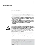
Page 19: ...h class I protection against electric shocks it is essential to install a protective earth conductor connect earth Connect the conductor to the terminal X5 before connecting the power supply to the UPS input All connections in the device including those for control interface remote control will be performed with the switches at rest and without any mains feed present UPS power line cut off Off It ...

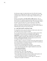
Page 20: ...n of the batteries will always be done by the customer and it is under his responsibility The relevant information on the batteries number capacity and voltage are indicated in the battery label pasted beside the nameplate of the equipment Strictly respect this data the battery polarity connection and the circuit diagram provided with this documentation The battery supply can involve the risk of e...

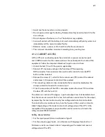
Page 21: ...led Remove the screws t1 which fix the terminal cover TB inside of the cabinet and remove it the power terminals will be revealed The connecting cables can be connected to the terminals located below the clamps and can be fixed to the aluminum rail Once the connection of the UPS is complete replace the cover TB and close the door PF with the lock CL The cable cross section of the bypass input and ...

Page 22: ... of protection installed at the primary winding of the transformer in cases were an short circuit in the secondary winding output of isolation transformer may occur Note that all neutral terminals for input output and battery are connected inside the UPS The cable routing or housing passages supplied fitted to the metal structure are those recommended to correctly fix the input output and bypass w...

Page 23: ... can cause irreversible damage to the equipment or accidents 4 2 Set up and installation 4 2 1 Unpacking and content checking On receiving the device make sure that it has not suffered any damage during transport Make all damage claims to your supplier or to our company Check the data in the nameplate which is fixed inside the front door PF and that it corresponds to that specified in the purchase...

Page 24: ...nd stor age If ordered with the UPS closed lead accumulators are built into the UPS or the battery cabinet To ensure problem free operation of the 10 20 kVA equipment you should not store for longer than 3 months and absolutely no longer than 6 months If longer storage is required the batteries must be recharged after the aforementioned periods Store batteries or equipment with built in batteries ...

Page 25: ...ong as the safety instruction requirements are fulfiled and the weights are considered as indicated in table 5 and 6 The UPS includes 2 leveling elements PB located near the front castors which serve to immobilise the unit once it is in place Open the front door PF of the cabinet and proceed as follows By hand loosen the leveling elements PB by turning them anti clockwise until they touch the floo...

Page 26: ...40 1 installation has to be provided with a feedback protection system e g a contactor which will prevent the appearance of voltage or dangerous energy in the input mains during a mains fault see Fig 18 and respect the wiring diagram of feedback protection There can be no deviation in the line that goes from the feedback protection to the UPS as the standard safety would be infringed Warning label...

Page 27: ...nce personnel to the presence of a UPS in the circuit Fig 18 Block diagram for the feedback protection application for the different configurations Fig 19 Single line diagram of parallel system connection UPS with protection panel and feedback protection ...

Page 28: ...e output terminals X6 to X9 As this is a device with class I protection against electric shocks it is essential to install a protective earth conductor connect earth Connect the conductor to the terminal X5 before connecting the power supply to the UPS input To connect the output cables to the respective terminals according to configuration of the available equipment Connection to the output Conne...

Page 29: ...nection with battery pack will be implemented with the supplied trunk cable by connecting one side to terminals X11 X23 and X12 of the UPS and the other one to terminals X47 X49 and X48 on the battery pack Always respect the stated polarity in the labeling of each part and in this manual The color of the cables red for positive black for negative blue for middle tap N and green yellow for earth bo...

Page 30: ...oops which can affect operational safety All of the terminals identified as protective earth bonding are joined together to the main protective earthing terminal and to the frame of the device 4 3 5 Interface relay contacts connector X32 The remote signal lines operate over low voltage To ensure safe and problem free communication install at a safe distance from the power supply lines to the UPS T...

Page 31: ... is closed 4 3 6 COM interface RS232 and RS485 connector X31 The serial communications interface operates over low voltage To ensure safe and trouble free communication install at a safe distance from the power supply lines to the UPS The X31 DB9 connector is used for communication to RS232 or RS485 standard connectors Both standards cannot be used simultaneously Both channels are in use for conne...

Page 32: ...ill be advisable to repeat the channel initialization sequence Physical structure of the RS485 Unlike other serial communication links this uses only 2 wires pins 4 and 9 of the female DB9 connector to perform the dialogue between the systems connected to the network The communication will be established by sending and receiving signals in differential mode which gives the system great immunity to...

Page 33: ... the two UPS devices Detailed information on emergency shutdown can be found in chapter 5 6 4 3 8 Parallel BUS connection X36 This section is only relevant for parallel systems For the correct parallel operation both UPS communicate to each other via the parallel BUS For redundancy purposes the BUS connection consists of 2 cables which are connected in a loop Connect the parallel BUS connection af...

Page 34: ... the BUS cables to the bottom of the UPS using the plastic clips below the communication interfaces Note Always use the original lines to ensure trouble free parallel operation Fig 23 Parallel BUS Connection ...

Page 35: ...dures apply to both UPS devices You can use the procedure described below step by step for the first UPS and then for the 2nd UPS until you see the message Close battery switch Now you can close both battery switches It is irrelevant which UPS starts first If the UPS connects to an external battery cabinet set the fuse holder switch of the battery cabinet Q8 to On If the power supply to the UPS ha...

Page 36: ...est Confirm YES Turn OFF UPS Confirm YES Turn ON UPS Back Battery Test ON OFF Control Main screen 0 0 screen 1 0 Ent Ent screen 1 1 Ent screen 1 2 Ent screen 1 3 Ent screen 1 0 Procedure start up shutdown Before continuing be sure that the LED indication c Inverter is working and is it green and b Unit on Bypass is turned OFF see Fig 25 Once the rectifier is completely working it initiates a proce...

Page 37: ...een 1 2 asking you to shut down the unit by pressing ENT see Fig 24 Turn the output switch Q2 to Off position Set the input switch Q1a to Off position Turn fuse holder switch from battery cabinet Q8 and or battery fuse holder switch or switch from UPS Q3 to Off Cut the power supply of the UPS and the bypass with the cut off or general switch on the header board The system will be completely deacti...

Page 38: ... 1 2 Start up procedure Table 3 Emergency Power Off EPO operation Note In parallel mode it is sufficient when the emergency shutdown is activated for one UPS 5 4 Bypass manual switch Maintenance 5 4 1 Principle of operation The integrated manual bypass of the UPS is a very useful element but unwarranted use can have irreversible consequences both for the UPS and for the loads connected to its outp...

Page 39: ...tch Q3 to Off In models with inde pendent battery pack s also turn Battery Fuse Holder Q8 of each pack to Off Set the input switch Q1a to Off position The UPS is supplying output voltage directly from the mains through the manual bypass The UPS is completely shut down and inactive 5 4 3 Transfer to normal operation Procedure for switching from maintenance bypass to normal operation In model with a...

Page 40: ...or alarm message to appear CLOSE BATTERY SWITCH Battery fuse holder switch or switch from UPS Q3 can only be turned On when the previous alarm message has been canceled DO NOT TRY to close any battery fuse holder switch at any other moment because this operation could damage the equipment and or possibly cause accidents They can only be turned on by following the quoted previous steps The UPS deli...

Page 41: ...ication ESC Escape key Return to previous screen cancel finish programming or other specified functions By pressing the right and left keys you will see the titles on the sub menus and can navigate between the different displays 6 1 1 Touch Screen The touch functionality of the screen can be used by touching the screen Simply type with your finger on the appropriate fields or text 6 2 Basic functi...

Page 42: ... are in the Parameters menu and in the process of setting any of them If so by pressing the ESC key the value will stop blinking and by pressing it a second time you will go back to the previous screen With the UPS in bypass mode use the ESC button to cancel alarms In this way the audible alarm is turned off Notes related with the screen map see Fig 27 Some screens have a certain number of charact...

Page 43: ...NT to enter into the subscreen Fig 27 screen 0 0 The input output battery voltage and the power flow screen 1 0 Ent screen 2 0 Ent screen 3 0 Ent screen 4 0 Ent Ent screen 5 0 MAIN CNTL Control Status of the unit MEAS Measures SET Settings ALARM Alarms DATA Datalogger Display messages menus and classification in submenus ...

Page 44: ...44 6 2 2 Menu structure ...

Page 45: ... screen menu 0 0 Screen 0 0 Main presentation screen with time and date indication Initialization After power on Use ESC key or Enter the Icon home on any screen of any submenu to go back to main screen Screen 0 0 Fig 28 Screen 0 0 Main Screen ...

Page 46: ...LE The battery test is not available PRESS ENTER Press ENTER to run the battery test EXECUTING The battery test is running SUCCESSFUL The battery test has been successful NOT SUCCESSFUL The battery test has not been successful Fig 29 Screen 1 0 Control status screen Fig 30 Confirm YES DO Battery Test Confirm YES Turn OFF UPS Confirm YES Turn ON UPS Back Battery Test ON OFF Control Main screen 0 0 ...

Page 47: ...47 Screen 1 1 Turn on UPS Screen 1 2 Turn off UPS Screen 1 3 Battery Test ...

Page 48: ...neutral display units 0 1 V Output current per each phase display units 0 1 A DC bus voltages positive and negative display units 0 1 V Battery voltages positive and negative display units 0 1 V Screen 2 2 Three phase inverter output voltages phases to neutral display units 0 1 V Inverter output current per each phase display units 0 1 A Three phase bypass voltages phases to neutral display units ...

Page 49: ...emperatures display units1 ºC Input apparent power of L1 display units 0 1 kVA Input apparent power of L2 display units 0 1 kVA Input apparent power of L3 display units 0 1 kVA Input active power of L1 display units 0 1 kW Input active power of L2 display units 0 1 kW Input active power of L3 display units 0 1 kW Total input apparent power and active power display units 0 1 kVA 0 1 kW Input power ...

Page 50: ...Active output power L2 display units 0 1 kW Active output power L3 display units 0 1 kW Total apparent and active powers display units 0 1 kVA and 0 1 kW Output power factor of each phase display units 0 01 Output load of three phases display units 0 1 Total input load and total output load display units 0 1 Calculated bridging time under the current load conditions display unit intervals 1 minute...

Page 51: ...en 3 1 Default settings The color scheme cannot be modified in the current software version Setting the time and date format The following display languages are available German English French Spanish Czech Chinese The modbus address for communication over RS232 485 is fixed In the current ...

Page 52: ...ation port 0 and port 2 The options are the following 1200 2400 4800 9600 19200 You can program the parity communication port 0 and port 2 The options are the following NONE ODD EVEN You can program the number of stop bits communication port 0 and port 2 The options are the following 1 2 You can program the protocol communication port 0 and port 2 The options are the following SEC MODBUS ...

Page 53: ...is Monday TUE The selected day to run the weekly the battery test is Tuesday WED The selected day to run the weekly the battery test is Wednesday THU The selected day to run the weekly the battery test is Thursday FRI The selected day to run the weekly the battery test is Friday SAT The selected day to run the weekly the battery test is Saturday SUN The selected day to the run weekly the battery t...

Page 54: ...t will run in October NOV The annual battery test will run in November DEC The annual battery test will run in December Screen 3 4 Advanced Setting In this section basic setting can be changed on the UPS There is the risk that changes made can affect the function or cause damage to the UPS Changes contained within this section should only be made by authorized personnel ...

Page 55: ...l Single parallel connection Unit is in single state Parallel Master parallel connection Unit is in master state Parallel Slave parallel connection Unit is in slave state Internal firmware versions of both Digital Signal Processor DSP Ver and micro controller uC Ver UPS Serial Number expressed with 10 characters Service information in the basic settings should be used ...

Page 56: ...voltage imbalance at the rectifier and the bypass input the current at the output and the battery charging current Furthermore the current of the battery and the input will be displayed 6 3 5 ALARMS level screen menu 4 0 When Alarm appears in the main menu you can only see one alarm but you can enter Alarm into the menu to check which alarms are in the current unit as in the following Screen 4 0 A...

Page 57: ...nit on bypass Initialise UPS 11 Some unit s blocked due to maintenance bypass 12 CAN BUS 1 Communication failure 13 CAN BUS 2 Communication failure 14 End of battery life 15 Battery temperature too high 16 Battery test not succeeded 17 Battery disconnection Shutdown restart 18 Mains phase rotation UPS start disabled 19 Bypass phase rotation UPS start disabled 20 EEPROM failure 77 Input voltage wro...

Page 58: ...tem UPS stop 72 Emergency power off No output voltage Byp stops 38 Output short circuit No output voltage 39 DSP internal error UPS block all 40 DC BUS voltage wrong Rectifier block Rectifier blocks 41 Rectifier blocked BLK UPS BLK rec 42 Rectifier desaturations Rectifier block 43 Voltage ramp error Rectifier block 44 DSP execution error Rectifier block 45 DSP internal error Rectifier block 46 Con...

Page 59: ...e 4 Alarm list displayed in the LCD panel Alarm 1 This message indicates that the rectifier is overloaded The rectifier overload appears when the input current of any phase is greater than the following ratio Iin ovl 0 326 x Pout Vout_p n Where Iin ovl is Overload Input Current A Pout is Rated Output Apparent Power VA Vout_p n is Rated Output Voltage phase to neutral V Alarm 2 This message indicat...

Page 60: ...Alarm 6 When the maintenance bypass switch is ON the UPS inverter will not be available Alarm 7 The mains failure occurs when in any phase the input voltage phase to neutral is out of the set margins 15 20 by default or the input frequency is out of the set margins 5 Hz by default Alarm 8 When the inverter or PFC temperature sensors measure temperatures over the programmed values 70 ºC by default ...

Page 61: ...he revision and replacement of some batteries will be necessary to be done via AEG PS customer service Alarm 16 The temperature of battery cabinet in case of separate battery cabinet or battery place in case of battery are located inside the UPS is higher than 40 ºC Alarm 17 If battery test automatic or manual is finished unsuccessfully this alarm will appear Alarm 18 Two possible reasons During t...

Page 62: ...he rectifier is shutdown immediately The UPS will make 3 attempts to restart then the rectifier will be blocked Alarm 24 When a mains phase rotation error is detected and under these conditions the rectifier is tried to be turned ON an input phase rotation alarm appears shutting down the rectifier Alarm 25 This message appears when the protection circuit for the avoidance of DC inverter IGBT overl...

Page 63: ...ars when an internal error in the digital signal processor DSP in the AC rectifier module occurs The inverter will shut down immediately Four attempts will be made to restart the UPS then the inverter will be blocked Alarm 34 This alarm appears when an output short circuit is detected limiting the output RMS current up to the set value 150 of nominal current by default The short circuit is detecte...

Page 64: ...us voltage over 450 V Positive DC bus voltage less than 325 V Negative DC bus voltage over 450 V absolute value Alarm 42 This alarm appears when the UPS is blocked for any reason This condition blocks also the rectifier Alarm 43 This message appears when at the rectifier the protection circuit has been tripped three times in order to prevent a rectifier IGBT overload The rectifier is now blocked A...

Page 65: ...BT inverter has been activated this message appears The inverter is now blocked Alarm 52 There is a command from the microprocessor to the DSP with no response from the inverter module of the DSP The inverter will block Alarm 53 After 5 times shutting down the inverter because of DSP Internal Error in the inverter module this alarm will appear indicating inverter blocked Alarm 54 This message appe...

Page 66: ...blocked for 30 seconds rectifier is also shut down Alarm 62 This message appears if the protection circuit to prevent IGBT overload has been activated and the inverter has been turned off The UPS will make 2 attempts to restart the inverter If the protection circuit is again activated the UPS will be blocked Alarm 63 After 3 times shutting down the UPS because of DSP Internal Error in the UPS modu...

Page 67: ...due to the management of system as a whole therefore this alarm is activated Alarm 70 In a parallel system the inverters of the equipment of the system connected at the output can be shutdown due to the management of system as a whole therefore this alarm is activated Alarm 71 This alarm is displayed when a combined shutdown of the PFC rectifier and inverter has been done at the same time there ar...

Page 68: ... 40 kVA The alarm 74 Loss of redundancy is displayed If the load of the system is higher than 60 kVA Beside the alarm 74 Loss of redundancy there will also be as a minimum among others alarm 2 Inverter overload in all the equipment in the system Alarm 75 This alarm can be displayed for two reasons Input contactor from the equipment faults it doesn t close properly It is shown when the DC bus volta...

Page 69: ...the keys you can move throughout the differ ent registers of this historic file The data logger file can save up to 100 historic registers Alarm on and off time The first row displays the date and time when the alarm occurred hh hour of alarm activation mm minutes of alarm activation ss seconds of alarm activation dd day of alarm activation mm month of alarm activation yy year of alarm activation ...

Page 70: ...d alarm dd day of deleted alarm mm month of deleted alarm yy year of deleted alarm The state for technical service to understand the condition of the different parts of the UPS at the moment the registered alarm was activated ...

Page 71: ...st also be isolated from the system Together with this the 3 pole circuit breakers for measuring the battery voltage located within the upper part of the equipment is released 7 1 1 Battery fuses There is significant risk if an attempt to switch either the battery switch or fuse box switch ON or I before the message Battery Switch Connect appears in the display an arc may result and the switch des...

Page 72: ...ommended that preventive replacement be carried out by authorized technical staff 7 2 Warranty conditions Changes in these operating instructions particularly as regards technical data and operating instructions can occur at any time and without notice If damage occurs due to not following the instructions any warranty claim will be void AEG PS accept no responsibility for consequential damage AEG...

Page 73: ...minal voltage 3 x 400 V 3 Ph N Precision stationary 1 transitory 2 load variations 100 0 100 Frequency Hz 50 60 0 05 without mains Synchronisation speed 1 Hz s Waveform sine wave Total harmonic distortion 0 5 linear load 1 5 non linear load Phase displacement 1 balanced load 2 50 unbalanced load Dynamic recovery time 10 ms 98 of static value Admissible overload 125 for 10 min 150 for 60 s Admissib...

Page 74: ...tion Voltage 3 x 400 V 3 Ph N Frequency Hz 50 60 general Max charging current 23 5 A 47 0 A 70 5 A Overall efficiency online mode up to 91 91 3 92 92 4 93 1 93 6 94 3 MaSS weight autonomy time Dimensions approx D x W x H mm 700 x 450 x 1 100 805 x 590 x 1 320 Footprint m2 0 315 0 475 Net weight without batteries kg 110 180 210 230 Integrated battery type 2 x 31 12 V 7 Ah 12 V 7 Ah 12 V 9 Ah 12 V 1...

Page 75: ...rated battery type 2x31 12 V 12 Ah 12 V 26 Ah Autonomy time min 32 20 14 20 14 8 Net weight approx kg 250 710 No 2 No 4 Dimensions approx D x W x H mm 700 x 450 x 1100 980 x 650 x 1322 Integrated battery type 2x31 12 V 18 Ah 12 V 40 Ah Autonomy time min 57 34 24 40 25 15 10 Net weight approx kg 410 1020 UPS cabinet Battery cabinet Height Depth Width Cabinet No 4 has no wheels Fig 33 General techni...

Page 76: ... from our company Do not install the machine in a corrosive or dusty atmosphere and never out of doors Do not obstruct the ventilation grilles nor introduce objects through these or other openings Leave a minimum free space of 25 cm around the machine for ventilation and air circulation Locations must be spacious well ventilated away from any heat sources and easy to access In addition to the vent...

Page 77: ...ment If the mains supply fails while the equipment is operating the output lines will continue to supply output voltage depending on the autonomy times provided by the batteries The 10 40 kVA UPS can be delivered with built in batteries Optionally batteries can be delivered separately and then installed at your location by authorized personnel For proper operation the battery cabinet must be locat...

Page 78: ...attery terminals as it involves a high risk It will result damage to the equipment and the battery Avoid mechanical exertion and impact Do not open or mutilate the battery Released electrolyte is harmful to the skin and eyes Do not dispose of a battery in a fire The battery may explode In case of contact between acid and parts of the body wash affected area immediately with plenty of water and cal...

Page 79: ...79 Notes ...

Page 80: ... Number Purchase date Emil Siepmann Str 32 59581 Warstein Belecke Germany Tel 49 180 523 4787 Fax 49 180 523 4789 www aegps com AEGPS Protect 2 33 2 0 EN 07 2012 V1 Due to our policy of continuous development the data in this document is subject to change without notice AEG is a registered trademark used under licence from AB Electrolux ...

Reviews: