


30
4.3.4. coNNEctioN maiN ProtEctivE EarthiNg
tErmiNal ( ) aNd ProtEctivE Earth boNdiNg
tErmiNal ( )
as this is a device with class I protection against electric shocks, it is essential to
install a protective earth conductor (connect earth ( )). Connect the conductor to
the terminal
(X5)
, before connecting the power supply to the UPs input.
Make sure that all the loads connected to the UPs are only connected to the
protective earth bonding terminal ( ). By not restricting the earthing of the load
or loads and/or the batteries case/s or cabinet/s to this
single point,
can lead to
ground loops which can affect operational safety.
all of the terminals identified as protective earth bonding ( ), are joined together,
to the main protective earthing terminal ( ) and to the frame of the device.
4.3.5. iNtErFacE rElay coNtacts, coNNEctor (X32)
The remote signal lines operate over low voltage. To ensure safe and problem free
communication, install at a safe distance from the power supply lines to the UPs.
The built in relays provide a digital signal over a potential free contact.
The permissible contact load is 6 a 30 VDC or 6 a 100 VaC. supplemental to the
DB9 connector you will find parallel screw terminals on the communication board.
remote signaling operates over fiver output relays (one is adjustable), the
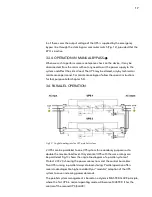
Fig.20: Connection example between a UPS and two battery cabinets


