background image


USER INTERFACE


2.


values and alarm and to clearly display the status of the relay.  


The front panel of the relay has three separate sections:


The LCD display and the keypad 

1. 


The LEDs 

2. 


The two zones under the upper and lower flaps 
 

3. 


2 buttons to read and 


Clear alarms messages 


5 buttons to modify the 

setting and read vaues 


2 × 16 alphanumerical 

backlit display


Trip led


Alarm led


Warning led


Power led


Figure 1: Front panel


Programmable led


User Guide                                                

HF9024

HF9024


relay from panel allows the user to easily enter relay settings, display measured 

  RS 232

Summary of Contents for DUA2.1

Page 1: ...Numerical Voltage Protection Relay Technical Guide and user manual HF9024 DUA2 1 ...

Page 2: ...ide and user manual Contents CONTENTS Handling Installation and Case Dimensions User Guide Menu Content Tables Technical Data and Curve Characteristics Application Guide NUMERICAL Voltage Relay Introduction HF9024 ...

Page 3: ...Introduction 5 HF9024 CONTENTS 1 INTRODUCTION 2 2 HOW TO USE THIS MANUAL 3 3 INTRODUCTION TO THE HF9024 4 4 MAIN FUNCTIONS ...

Page 4: ...Introduction 1 INTRODUCTION The Voltage relay type HF9024 is a numerical relay HF9024 ...

Page 5: ...oduction to the relay HF9024 Handling installation and case dimensions Precautions to be taken when handling electronic equipment HF9024 User Guide of the relay as A detailed description of the features HF9024 Technical data and Comprehensive details on nominal values setting ranges Specifications HF9024 Commissioning and Maintenance Guide Guide to commissioning problem solving and maintenance of ...

Page 6: ... made available The relay is equipped on the front panel with a liquid crystal display LCD with 2 x 16 back lit alphanumerical characters a tactile 7 button keypad to access all settings clear alarms and read measurements and 11 LEDs that indicate the status of the relay In addition the use of the RS485 communication port by using protocol mode bus makes it possible to read reinitialize and change...

Page 7: ...ection 27 Phase under voltage AND OR logic 59 Phase over voltage AND OR logic 59N Zero sequence over voltage 47 Negative sequence over voltage Remote communication RS485 port Local communication RS232 port Event recording 250 Fault recording 25 Disturbance recording 5 Setting group 1 Circuit Breaker Control Output relay latching HF9024 27D Positive sequence under voltage Delta U Delta T Blocking l...

Page 8: ...Handling Installation and Case Dimensions HANDLING INSTALLATION AND CASE DIMENSIONS HF9024 ...

Page 9: ...1 GENERAL CONSIDERATIONS 2 1 1 Receipt of relays 2 1 2 Electrostatic discharge ESD 2 2 HANDLING OF ELECTRONIC EQUIPMENT 3 3 RELAY MOUNTING 4 4 UNPACKING 5 5 STORAGE 6 6 DIMENSIONS 7 7 Communication 8 7 1 RS232 Port 8 7 2 RS485 port 8 8 Earthing 8 HF9024 ...

Page 10: ... case and the internal module should not be withdrawn unnecessarily When handling the module outside its case care should be taken to avoid contact with components and electrical connections If removed from the case for storage the module should be placed in an electrically conducting antistatic bag There are no setting adjustments within the module and it is advised that it is not unnecessarily d...

Page 11: ...r edges of the printed circuit board Avoid touching the electronic components printed circuit track or connectors 3 Do not pass the module to another person without first ensuring you are both at the same electrostatic potential Shaking hands achieves equal potential 4 Place the module on an antistatic surface or on a conducting surface which is at the same potential as yourself 5 Store or transpo...

Page 12: ...ither individually or as part of a panel rack assembly Modules should remain protected by their metal case during assembly into a panel or rack For individually mounted relays an outline diagram is supplied in following of this chapter showing the panel cut outs and hole centers HF9024 ...

Page 13: ... be handled by skilled personnel The installation should be clean dry and reasonably free from dust and excessive vibration The site should be well lit to facilitate inspection The relay that has been removed from the case should not be left in a situation where that is exposed to dust or damp This particularly applies to installation which is being carried out at the same time as construction wor...

Page 14: ... retained The action of the de humidifier crystals will be impaired if the bag has been exposed to ambient conditions and may be restored by gently heating the bag for about an hour prior to replacing it in the carton Dust which collects on a carton may on subsequent unpacking find its way into the relay in damp conditions the carton and packing may become impregnated with moisture and the de humi...

Page 15: ...102 4 HF9024 6 CASE DIMENSIONS The relay is available in a 4U metal case for panel or flush mounting Weight 1 8 Kg External size Height case 152 mm Front panel 177 mm Width case 97 mm Front panel 103 mm Depth case 226 mm Front panel case 252 mm ...

Page 16: ...e Screen Overall braid PVC sheathed Linear capacitance between conductor and earth 100pF m 8 Earthing Each equipment must be connected to a local earth terminal by the intermediary of a M4 earth terminal We recommend a wire of minimal section of 2 5 mm with annular terminals on the side of the equipment Because of the limitations of the annular terminals the possible maximum section is of 6mm by w...

Page 17: ...User Guide User Guide HF9024 ...

Page 18: ...wo areas under the top and bottom flaps 6 3 PASSWORD 7 3 1 Password protection 7 3 1 1 Password entry 7 3 1 2 Changing the password 7 3 1 3 Change of setting invalidation 8 4 DISPLAYS OF ALARM WARNING MESSAGES 8 4 1 Electrical Network Alarms 8 4 2 Relay Hardware or Software Warning Messages 10 HF9024 CONTENTS 1 PRESENTATION OF HF9024 RELAY 2 ...

Page 19: ... for 1 and 5 Amps rated CTs On each one of these relay HF9024 relay continuously measure phase and earth currents and take into account the true RMS current value up to 10th harmonic at 50 Hz Output relays are freely configurable and can be activated by any of the control or protection functions available in the relay Logic inputs can also be assigned to various control functions On their rear ter...

Page 20: ...e LEDs 2 The two zones under the upper and lower flaps 3 2 buttons to read and Clear alarms messages 5 buttons to modify the setting and read vaues 2 16 alphanumerical backlit display Trip led Alarm led Warning led Power led Figure 1 Front panel Programmable led User Guide HF9024 HF9024 relay from panel allows the user to easily enter relay settings display measured RS 232 ...

Page 21: ...a value modification of settings 2 2 LEDs The top four LEDs indicate the status of the relay Trip condition alarm LED equipment failure Power The four lower LEDs are freely programmable by the user and can be assigned to display a threshold crossing for example available for all models or to show the status of the logic inputs The description of each one of these eight LEDs located in the left sid...

Page 22: ...rmation defines the product in a way that is unique In all your requests please make reference to these two numbers Under the model and serial number you will find information about the level of voltage of the auxiliary supply and the nominal earth current value There is RS232 port available under the lower flap in the relay This RS232 port can be used to plug a laptop loaded with setting software...

Page 23: ...Alarm LED 2 lights up Alarm messages generated by the electrical power network Electrical Network Alarms Any crossing of a threshold instantaneous or time delay generates an electrical network alarm The involved threshold is indicated Regarding the phase thresholds the phase designation is also displayed If several alarms are triggered they are all stored in their order of appearance and presented...

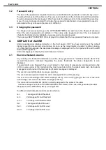
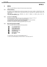
Page 24: ...ccess To The Menu Navigation through the different menus is done pressing the arrow keys The organization of the menus is shown in figure as follows There is need of an unlock key when reading parameters and measured values Modification of a parameter requires entering a password Should an error be made in entering a parameter press to cancel Menu Contents Description The menu of HF1021relay is di...

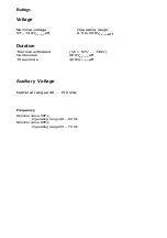
Page 25: ...0Vph ph eff Nominal value 50Hz Operating range 40 60 Hz Nominal ranges 48 150 Vdc 10 seconds 300Vph ph eff Nominal value 60Hz Operating range 50 70 Hz Nominal voltage Operating range 57 130Vph ph eff 0 5 to 200Vph ph Ratings Voltage Duration Auxiliary Voltage ...

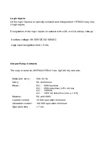
Page 26: ...tion minimum Unloaded contact 100 000 operation minimum Operation time 7 ms Output Relay Contacts Energization of the logic inputs is realised with a DC or ACauxiliary voltage The output contacts ofHF9024 RELAY are AgCdO dry contacts All the logic inputs are optically isolated and independent HF9024 relay has 2 logic inputs Auxiliary voltage 48 150VDC 32 100VAC Logic input recognition time 5 ms ...

Page 27: ... Nominal is with 50 of the optos energised and one relay per card energised Optically isolated inputs Reference voltage Current per logic input BURDENS Voltage circuits REFERENCE VOLTAGE VN VN 57 200V 0 25 VA VN 220 480V 0 36 VA ...

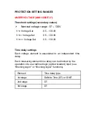
Page 28: ...c1 or Blocking logic2 functions Element Time delay type 1st stage Definite Time DT or IDMT 2nd stage DT 3rd stage DT Each voltage element is associated to an independent time delay V Voltage Set 0 5 130 0V V Voltage Set 0 5 130 0V V Voltage Set 0 5 130 0V Time delay settings PROTECTION SETTING RANGES UNDERVOLTAGE ANSI CODE 27 Threshold settings secondary values ...

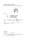
Page 29: ...rating time in seconds TMS time Multiplier Setting V applied input voltage Vs relay setting voltage NOTE this equation is only valid for Vs V ratio than 0 95 Hysteresis Hysteresis 1 02 1 05 NOTE this range is a percentage value of the pickup value of the undervoltage elements TMS 0 5 100 0 by step 0 5 TRESET only DT 40ms ...

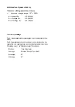
Page 30: ...s associated to an independent time delay Each measuring element time delay can be blocked by the operation of a user defined logic optical isolated input see Blocking logic1 or Blocking logic2 functions Element Time delay type 1st stage Definite Time DT or IDMT 2nd stage DT 3rd stage DT OVERVOLTAGE ANSI CODE 59 Threshold settings secondary values ...

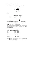
Page 31: ...1 TMS 0 5 100 0 by step 0 5 TRESET only DT 0 00 100 00s When the V is associated with IDMT curve the recommended maximum setting value should be less or equal to max setting range divided by 20 Definite time delay characteristics tV 0 00 599 00s tV 0 00 599 00s tV 0 00 599 00s NOTE this range is a percentage value of the pickup value of the overvoltage elements teresis Hysteresis 100 Hys 95 V NOTE...

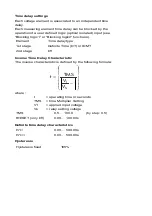
Page 32: ...ement Time delay type 1st stage Definite Time DT or IDMT 2nd stage DT Inverse Time Delay Characteristic The inverse characteristic is defined by the following formula 1 V V TMS t S 1 where t operating time in seconds TMS time Multiplier Setting V1 applied input voltage Vs relay setting voltage TMS 0 5 100 0 by step 0 5 tRESET only DT 0 00 100 00s Definite time delay characteristics tV1 0 00 599 00...

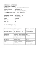
Page 33: ...IEC Baud rate 300 600 1200 2400 4800 9600 19 200 or 38 400 bits s Modbus Baud rate 64000 bits s Kbus Parity Even Odd or Without Modbus RTU Stop bits 0 or 1 or 2 Modbus RTU Remote address 0 255 step 1 Modbus RTU COMMUNICATIONS FRONT PORT RS232 Front port Communication Parameters Fixed Protocol Modbus RTU Address To be specified in the COMMUNICATIONS menu of therelay REAR PORT RS485 ...

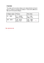
Page 34: ... 480V step 10V 220 480V step 10V The primary and secondary rating can be independently set foreach set of VT inputs for example the residual VT ratio can bedifferent to that used for the phase voltages Voltage ranges Primary Secondary VT RATIOS By costomer order ...

Page 35: ...amable input1 ogramable input2 49 32 27 33 37 35 WD 36 42 5 43 3 44 RL1 1 45 11 9 RL2 7 50 15 RL3 13 Programmable output 19 RL4 17 Programmable output Case eart h connection 29 30 31 21 23 2 Link terminals 30 and 32 if the relay is connected at Revision V 002 38 40 Programmable output RL5 HF9024 DUA2 1 Approved By Araghi Date 99 10 27 Page 1 1 Checked By Drawn By ...

Page 36: ...nput1 ogramable input2 32 27 33 37 35 WD 36 1 9 RL2 7 RL3 13 Programmable output 19 RL4 17 Programmable output Case eart h connection 29 30 31 21 23 2 Link terminals 30 and 32 if the relay is connected at Revision V 002 38 40 Programmable output RL5 HF9024 DUA2 1 Approved By Araghi Date 99 10 27 Page 1 1 Checked By Drawn By 41 42 43 44 45 46 49 50 3 5 RL1 ...

Reviews: