background image


        --------------------------------------------------------------------------16/21------------------------------------------------------------------------------------


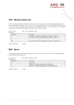
TOR – Maximal reading time 
 

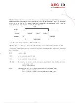
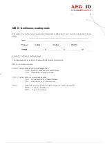
TOR is a timing parameter of the reader. It is used in operation mode 2 to limit the reading attempts. The 
maximal time for one reading cycle is TOR * TB. The timing parameter TB (Time base) has the default value 
100 ms. One reading cycle can consist of several single reading attempts, until one is successful, or TOR time 
is expired. From external one reading cycle looks like one single reading.  
 
Input format: 


TOR <SP> Parameter <CR> 

Parameter: 

Parameter 

Function 

Limitation of the reading attempts to approx.2 times TB 

Limitation of the reading attempts to approx.3 times TB 

... 


999 

Limitation of the reading attempts to approx. 999 times TB 

 
Output (Example): 

2 <CR> 


BUZ – Buzzer 
 

The successful reading of a transponder can be shown by an acoustic signal. The buzzer is activated or deac-
tivated with the BUZ command. 
 
Input format: 


BUZ <SP> Parameter <CR> 

Parameter:  

Parameter 

Function 

Buzzer off 

Buzzer on, output in Good and Bad Read case 

Buzzer on, Good Read indication only (Default value) 

 
Output (Example): 

2 <CR> 


Summary of Contents for ARE i5 MTL

Page 1: ... 1 21 Manual for the RFID reader ARE i5 MTL RS 232 ...

Page 2: ...fic answer 12 Answer to a parameter input 12 Answer to a parameter request 12 Empty input line 12 Capital and small letters 12 Carriage return 13 VER Software version of the reader 13 MD Operation mode 13 GT Reading command get tag 14 CID Suppression of equal ID codes 15 CN Suppression of no reads 15 NID Error protection on reader level 16 TOR Maximal reading time 16 BUZ Buzzer 17 ALGO Algorithm 1...

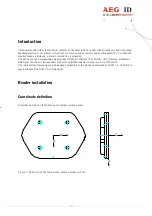
Page 3: ...ial The device can read transponders appropriate DIN ISO 11784 11785 FDX B HDX Destron Datamars Additional Trovan and transponders with ASK 64bit Manchester coding e g Chip EM 4102 The implemented command set is downward compatible to the standard command set ASB 1 0 The ARE i5 uses a subset of the ASB 1 0 command set Reader installation Coordinate definition In further description the following c...

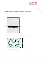
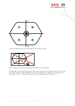
Page 4: ...tion of the antenna When mounting on a concrete wall it is to notice that this wall may contain reinforcing iron in an unfavorable geometry In this case only a power dissipation occurs because of the distance of the iron structure but not a complete short circuit In this configuration the reading range is lower than specified and the current consumption is higher than normal metal Figure 3 False h...

Page 5: ... minimum distances shown in figure 4 and figure 5 200 200 570 Reading direction metal free zone Figure 4 Minimum distance of the antenna to structures of metal drawing in plane x z 290 570 metal free zone Figure 4 Minimum distance of the antenna to structures of metal drawing in plane x y ...

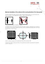
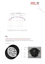
Page 6: ...tional orientation transponder antenna The reading field is a complex three dimensional function which is relevantly influenced by the orientation of the transponder With parallel orientation see figure 6 and low interference the reading field in front of the antenna shown in figure 7 results A A B BB 10 5 0 5 10 15 15 B AA Figure 7 Reading field above the longitudinal axis AA and transverse axis ...

Page 7: ...e transponder over the antenna A transponder has to be long enough in the active reading area to achieve a reliable reading result The max imum reading distance will be achieved only in stationary operation The reading range is reduced with a transponder in motion Therefore the transponder has to be passed closer at the antenna ...

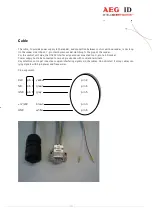
Page 8: ...h a RS232 interface For power supply 12 or 24 VDC are necessary Check the identification plate The corresponding signals are connected to a 7 pin Hiraschmann plug on the reader side The plug is IP 65 protected Pin assignment 4 12 24 V 5 GND 2 RxD 3 TxD 5 GND 4 5 6 1 2 3 ...

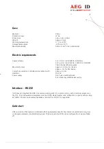
Page 9: ...t side the RS232 interface signals are connected to a 9 pin Sub D socket Power supply has to be connected to two single strands with cord end terminals Pay attention not to get inductive coupled interfering signals via the cables Do not install it along cables car rying signals with high power and frequencies Pin assignment RxD pin 2 yellow pin 2 TxD pin 3 green pin 3 GND pin 5 grey pin 5 12 24V b...

Page 10: ...antenna off approx 0 15A Interface RS 232 Power supply Don t use a switched mode but a linear regulated power supply Interface RS 232 Via the serial interface the ARE i5 is communicating with it s control unit e g with a terminal program on the PC The configuration parameters must be 19200 Baud transfer rate 8 data bits no parity and one stop bit 8N1 There is no hardware handshake Xon Xoff or RTS ...

Page 11: ...x35 0x35 the command RST as 0x52 0x53 0x54 Input The protocol has the following format Command SP Parameter CR The space character SP is used as partition between command and parameter The CR character is used as end of the command Commands without parameters e g GT or RST are shorter Command CR Output Every input that ends with a CR is answered by the reader Following different answers are possib...

Page 12: ... Answer to a parameter request Parameter values can be read by using the parameter command without a parameter value Example Command MD CR Answer 2 CR Empty input line If only a CR sent the reader answers with a CR Example Command CR Answer CR Capital and small letters The reader interface does not act case sensitive Captial and small letters are treated the same Carriage return The reader does no...

Page 13: ...t is changed to continuous reading mode the reader does not respond to commands any longer It is exclusively sending transponder codes or no read messages To switch it back to command mode it has to be restarted GT Reading command get tag The command GT starts a reading attempt See chapter Operation modes MD 2 Command mode Input format GT CR Output Example Depending on the parameter settings and t...

Page 14: ... a no read Sequence of reading cycles Output sequence after filtering with CN 0 and CID 1 Output sequence after filtering with CN 1 and CID 1 N N N A A A A N N N N N A N N A N N N A A A N A A B A C C C N N N A N B A C A B A C Table 1 Example for the effect of the filter function CID Effect The filter is active immediately after the command CID SP 1 CR Annotation In the following cases the comparis...

Page 15: ... a no read appears NID Error protection on reader level NID specifies the amount of equal reading results necessary for a successful reading cycle If the parameter NID is set to the value 1 the reader internally has to read two times the same transponder number before sending one successful reading result Input format NID SP Parameter CR Parameter Parameter Function 0 One out of one no effect 1 Tw...

Page 16: ...le reading Input format TOR SP Parameter CR Parameter Parameter Function 2 Limitation of the reading attempts to approx 2 times TB 3 Limitation of the reading attempts to approx 3 times TB 999 Limitation of the reading attempts to approx 999 times TB Output Example 2 CR BUZ Buzzer The successful reading of a transponder can be shown by an acoustic signal The buzzer is activated or deac tivated wit...

Page 17: ...arameter CR Parameter Parameter Function 01 Trovan 02 Marin ASK 64 Bit 04 Datamars 08 Destron 10 ISO Hdx 20 ISO Fdx 40 PSK2 80 PSK1 03 Trovan Marin FF All Algorithms activated Default value Output Example FF CR CM Measurement signal strength of the transponder noise level The output of the antenna receive path is used to calculate a RMS value The source of this signal is the transmission power of ...

Page 18: ... defined Operation mode 0 Command mode Operation mode 2 Continuous reading mode In the following chapters their functionality is described MD 2 Command mode The communication partner is sending the command Get tag GT CR to start a reading attempt The result the transponder code or a no read message is sent back In operation mode 2 the exciter is normally switched off Triggered by the GT command in...

Page 19: ...with TOR 0 Attention During a reading cycle during the TOR time there is no no read output in operation mode 2 This operation mode is factory setting For further configuration and adaption to the application use the fol lowing commands MD 2 Command mode CID 0 No suppression of equal ID codes CN 0 No suppression of no read messages TOR XYZ Maximal time the exciter is on Maximal reading time x 0 1s ...

Page 20: ...d with the following commands MD 0 Continuous reading CID X Setting of the equal ID code suppression CID 0 Equal ID codes are read several times CID 1 Suppression of equal ID codes CN X Setting of the no read message output CN 0 No suppression of no read messages CN 1 Suppression of no read messages NID X Additional error protection Internal comparison of the transponder NID 0 1 out of 1 selection...

Page 21: ...Marketing 49 0 731 140088 0 Fax 49 0 731 140088 9000 e mail sales aegid de http www aegid de Notification of changes revision Date description of changes Editor 00 29 08 2007 First revision 01 31 01 2011 English translation MK 02 01 06 2012 New parameter ALGO MK 03 16 12 2016 12 and 24 V reader manual in one MD parameter is not saved in MTR15 version MK ...

Reviews: