16
English
GB
- if the blade becomes twisted or misaligned in the cut, the teeth at
the back edge of the blade can dig into the top surface of the wood
causing the blade to climb out of the kerf and jump back toward the
operator.
Kickback is the result of saw misuse and/or incorrect operating proce-
dures or conditions and can be avoided by taking proper precautions
as given below.
Maintain a firm grip with both hands on the saw and position
your arms to resist kickback forces. Position your body to eit-
her side of the blade, but not in line with the blade.
Kickback
could cause the saw to jump backwards, but kickback forces can be
controlled by the operator, if proper precautions are taken.
When blade is binding, or when interrupting a cut for any
reason, release the trigger and hold the saw motionless in
the material until the blade comes to a complete stop. Never
attempt to remove the saw from the work or pull the saw
backward while the blade is in motion or kickback may Occur.
Investigate and take corrective actions to eliminate the cause of blade
binding.
When restarting a saw in the workpiece, centre the saw blade
in the kerf and check that saw teeth are not engaged into the
material.
If saw blade is binding, it may walk up or kickback from the
workpiece as the saw is restarted.
Support large panels to minimise the risk of blade pinching
and kickback.
Large panels tend to sag under their own weight.
Supports must be placed under the panel on both sides, near the line
of cut and near the edge of the panel.
Do not use dull or damaged blades.
Unsharpened or improperly
set blades produce narrow kerf causing excessive friction, blade
binding and kickback.
Blade depth and bevel adjusting locking levers must be tight
and secure before making cut.
If blade adjustment shifts while
cutting, it may cause binding and kickback.
Use extra caution when sawing into existing walls or other
blind areas.
The protruding blade may cut objects that can cause
kickback.
Guard function
Check guard for proper closing before each use. Do not
operate the saw if guard does not move freely and enclose
the blade instantly. Never clamp or tie the guard so that the
blade is exposed.
If saw is accidentally dropped, guard may be
bent. Check to make sure that guard moves freely and does not touch
the blade or any other part, in all angles and depths of cut.
Check the operation and condition of the guard return spring.
If the guard and the spring are not operating properly, they
must be serviced before use.
Guard may operate sluggishly due to
damaged parts, gummy deposits, or a builup of debris.
Assure that the base plate of the saw will not shift while
performing the “plunge cut” when the blade bevel setting
is not at 90°.
Blade shifting sideways will cause binding and likely
kick back.
Always observe that the guard is covering the blade before
placing saw down on bench or floor.
An unprotected, coasting
blade will cause the saw to walk backwards, cutting whatever is in its
path. Be aware of the time it takes for the blade to stop after switch
is released.
Riving knife function
Use the appropriate saw blade for the riving knife.
For the
riving knife to function, the body of the blade must be thinner than
the riving knife and the cutting width of the blade must be wider
than the thickness of the riving knife.
Adjust the riving knife as described in this instruction manu-
al.
Incorrect spacing, positioning and alignment can make the riving
knife ineffective in preventing kickback.
Always use the riving knife, even when „plunge cutting“.
The
riving knife is being pressed upwards during plunge cutting and
springs back automatically into the kerf after plunge cutting when
you move the saw forward.
For the riving knife to work, it must be engaged in the
workpiece.
The riving knife is ineffective in preventing kickback
during short cuts.
Do not operate the saw if riving knife is bent.
Even a light
interference can slow the closing rate of a guard.
Wear ear protectors.
Exposure to noise can cause hearing loss.
Always wear goggles when using the machine. It is recommended to
wear gloves, sturdy non slipping shoes and apron.
The dust produced when using this tool may be harmful to health.
Do not inhale the dust. Use a dust absorption system and wear a
suitable dust protection mask. Remove deposited dust thoroughly,
e.g. with a vacuum cleaner.
Appliances used at many different locations including open air should
be connected via a residual current device (FI, RCD, PRCD) of 30mA
or less.
Before doing any work on the machine, pull the plug out of the
socket.
Only plug-in when machine is switched off.
Do not use saw blades not corresponding to the key data given in
these instructions for use.
Keep mains lead clear from working range of the machine. Always
lead the cable away behind you.
Before use check machine, cable, and plug for any damages or
material fatigue. Repairs should only be carried out by authorised
Service Agents.
Do not use saw blades not corresponding to the key data given in
these instructions for use.
Please do not use abrasion disks in this machine!
When sawing aluminium, the following measures must be taken for
safety reasons:
– Pre-connect a residual current device (FI, RCD, PRCD.
– Connect the machine to a suitable dust extractor.
– Aluminium must only be sawed with the special saw blades
designed for this purpose.
– When sawing panels, they must be lubricated with petroleum,
thin-walled profiles (up to 3 mm) can be sawed without lubrication.
SPECIFIED CONDITIONS OF USE
The plungecut circular saw can be used for sawing solid wood,
bonded wood, glued veneer, materials similar to wood, aluminium
profiles, Non-ferrous metals and plastics.
Do not use this product in any other way as stated for normal use.
Summary of Contents for 41091601
Page 1: ...TS 55 E ...
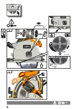
Page 4: ...1 1 2 2 3 2 3 1 1 click lock I 2 1 ...
Page 5: ...2 1 I 4 5 click 2 2 3 mm Test EN 847 1 ...
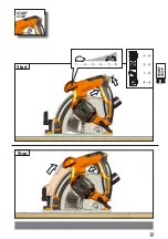
Page 6: ...3 II START STOP Stop 1 2 3 4 5 6 START STOP 1 2 2 1 Start ...
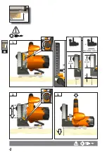
Page 7: ...4 III 2 2 3 1 1 3 max 55 mm x x Ident Nr 4932 3525 58 max 55 mm x ...
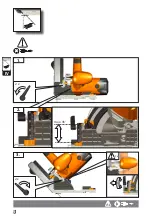
Page 9: ...6 IV 1 2 x 3 max 45 2 x 2 1 2 2 x ...
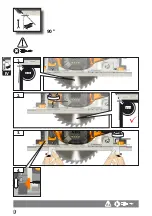
Page 11: ...8 4 IV 90 90 00 1 3 90 00 2 ...
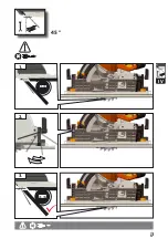
Page 12: ...9 IV 45 2 45 00 1 45 00 3 ...
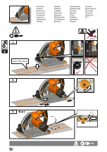
Page 13: ...10 1 2 x Start 2 3 V Ident Nr 4932 3525 58 90 00 ...
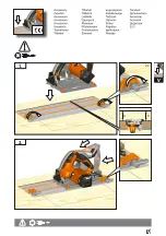
Page 14: ...11 1 2 V 2 x x x ...
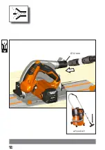
Page 15: ...12 AP 300 ELCP VI Ø 32 mm ...
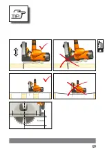
Page 16: ...13 VII 55 mm ...
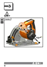
Page 17: ...14 VIII Service ...

