background image

UNO-127 User Manual

10

2.2.2

Power Connector

UNO-127 comes with a Phoenix connector that carries 10 - 30 V

DC

 external power

input, and features reversed wiring protection. Therefore, the system will not accrue

damage from reversed polarity of ground lines and power lines. (Please refer to User

Manual - Appendix A.1 for pin assignments)

2.2.3

LAN: Ethernet Connector 

UNO-127 is equipped with two 1 Gigabit LAN controllers. Intel i210 Ethernet control

-

ler  that  complies  with  IEEE  802.3u  10/100/1000  Base-T  is  used  as  the  controller

chip. The Ethernet port is a standard RJ-45 jack. Additionally, LED indicators are pro-

vided on the front of the device to indicate the system's Link (off/green/orange) and

Active  (green)  status.  (Please  refer  to  User  Manual- Appendix A.2  for  pin  assign

-

ments.)

2.2.4

USB Connector

UNO-127 features 2 x USB ports that comply with USB EHCI, 3 for Rev. 3.2 specifi

-

cations. The USB connectors support plug-and-play and hot-swap- ping functionality

for  external devices. Additionally,  this  can be  enabled/disabled  in  the BIOS menu.

(Please refer to User Manual- Appendix A.3 for pin assignments.)

2.2.5

Display Connector

The UNO-127 provides 1 x HDMI connector for resolution interface 1920 x 1080 @

60Hz. (Please refer to User Manual- Appendix A.4 for pin assignments.)

2.2.6

COM Connector

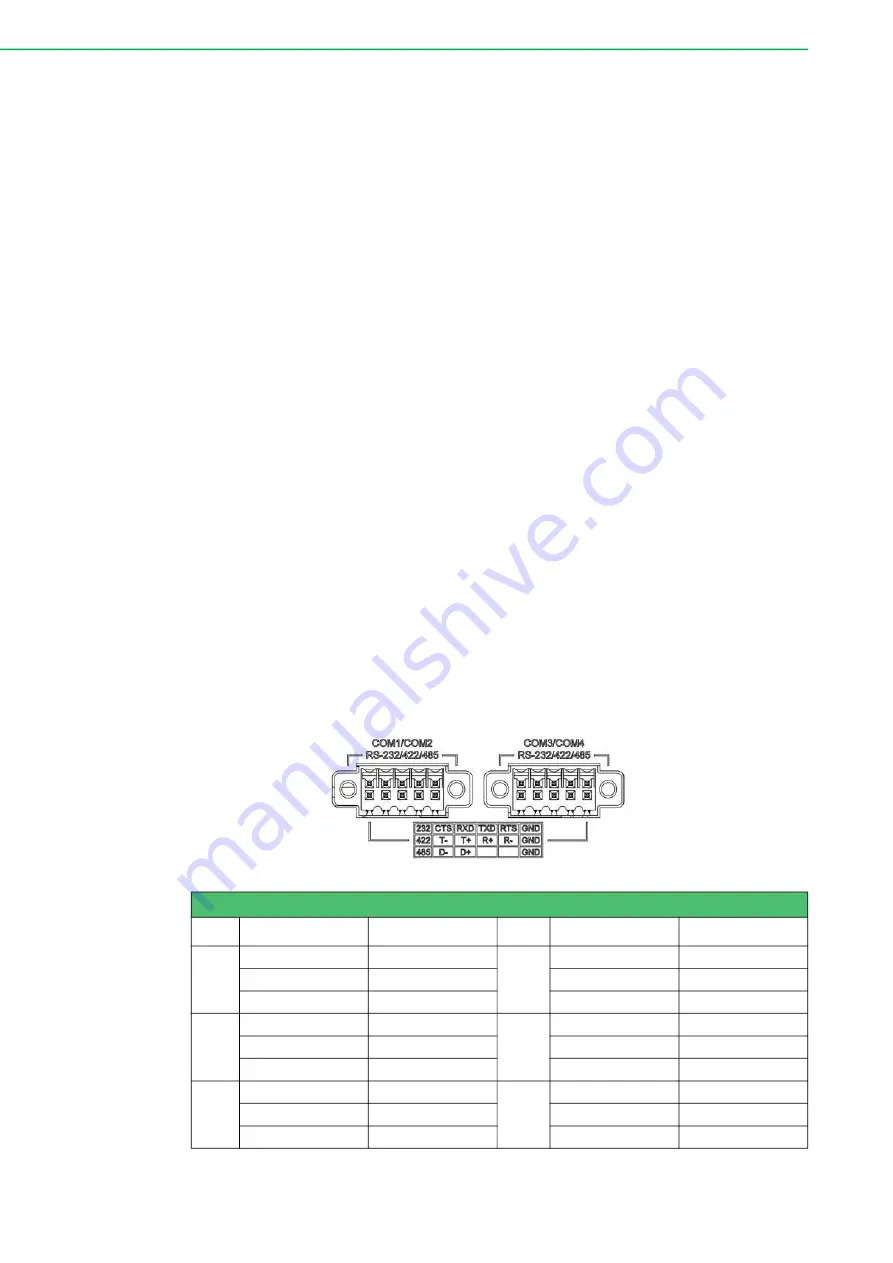
UNO-127-RS1EA  has  4 x COM RS232/422/485  ports  of terminal block type. They

offer trans- mission speeds of 50 ~115.2 kbps. The default mode for both COM ports

(COM1&COM2) is RS-232 Mode. Settings can be adjusted via an on-board switch

(SW1). (Please refer to User Manual- Appendix A.8 for RS232/422/485 settings).

Table 2.2: COM Connector Pin Assignments

Pin

COM1 Mode

Signal Name

Pin

COM2 Mode

Signal Name

1

RS232

CTS

2

RS232

CTS

RS422

T-

RS422

T-

RS485

D-

RS485

D-

3

RS232

RXD

4

RS232

RXD

RS422

T+

RS422

T+

RS485

D+

RS485

D+

5

RS232

TXD

6

RS232

TXD

RS422

R+

RS422

R+

RS485

RS485


Summary of Contents for UNO-127

Page 1: ...User Manual UNO 127 Intel Atom Elkhart Lake x6413E Compact Fanless Edge Controller...

Page 2: ...respective owners Support For more information on this and other Advantech products please visit our websites at http www advantech com For technical support and service please visit our support websi...

Page 3: ...T UNO127E22B2505 T UNO127E22B2506 T UNO127E22B2507 T UNO127E22B2508 T UNO127E22B2509 T UNO127E22B2510 T UNO127E22B2511 T UNO127E22B2512 T UNO127E23B2201 T UNO127E23B2202 T UNO127E23B2203 T UNO127E23B2...

Page 4: ...software used etc Note anything abnormal and list any onscreen messages displayed when the prob lem occurs 2 Call your dealer and describe the problem Please have your manual product and any helpful i...

Page 5: ...support to obtain the latest product information 2 Contact your distributor sales representative or Advantech s customer service center for technical support if you need additional assistance Please...

Page 6: ...on nel The power cord or plug is damaged Liquid has penetrated the equipment The equipment has been exposed to moisture The equipment is malfunctioning or does not operate according to the user manual...

Page 7: ...r dessus Ne placez rien sur le c ble d alimentation 9 Toutes les mises en garde et tous les avertissements sur l quipement doivent tre not s 10 Si l quipement n est pas utilis pendant une longue p rio...

Page 8: ...r l quipement peut tre alt r 19 L quipement ne contient aucune pi ce r parable par l utilisateur Ne pas ouvrir retourner au fabricant pour r paration 20 Ne bloquez pas les ou es de ventilation 21 Il s...

Page 9: ...r 9 2 2 1 UNO 127 Base Unit 9 Figure 2 3 Front Panel of UNO 127 9 Figure 2 4 Top View of UNO 127 9 2 2 2 Power Connector 10 2 2 3 LAN Ethernet Connector 10 2 2 4 USB Connector 10 2 2 5 Display Connect...

Page 10: ...ble A 3 USB 3 0 Connector Pin Assignments 23 A 4 HDMI Connector CN1 24 Table A 4 HDMI Display Connector 24 A 5 M 2 Connector 24 Table A 5 M 2 B Key Connector Pin Assignments 24 A 6 mPCIe Connector MIN...

Page 11: ...Chapter 1 1 Overview This chapter provides an overview of UNO 127 specifications Sections include Introduction Safety Precautions Accessories Hardware Specifications Dimensions...

Page 12: ...ssis whenever you are working on it Do not connect while the power is on A sudden rush of power can damage sensitive electronic components Only experienced electronics personnel should open the chassi...

Page 13: ...BIOS AMI EFI X64 Watchdog Timer Programmable 255 levels timer interval from 1 to 255 sec Hardware Security TPM 2 0 Processor Intel Atom Quad core x6413E 1 5GHz Memory 4 GB 8 GB DDR4 2666 MHz onboard U...

Page 14: ...20 60 C 4 140 F with 0 7m s airflow Storage Temperature 40 85 C 40 185 F Relative Humidity 10 95 RH 40 C 104 F non condensing Shock Protection Operating IEC 60068 2 27 50G half sine 11ms Vibration Pr...

Page 15: ...5 UNO 127 User Manual Chapter 1 Overview 1 4 7 Dimensions 33 5 x 70 x 100 mm W x D x H mm Figure 1 1 UNO 127 Dimensions Figure 1 2 UNO 127 Dimensions With UNO 127 RS1EA Optional Extension kit...

Page 16: ...UNO 127 User Manual 6...

Page 17: ...apter shows how to setup the UNO 127 s hardware func tions including connecting peripherals setting switches and indicators Sections include Introduction External I O Connector Internal I O Connector...

Page 18: ...monstrates the location of UNO 127 s motherboard s key components and internal external connectors Figure 2 1 Diagram of Connector Locations on UNO 127 Top Side Figure 2 2 Diagram of Key Components Lo...

Page 19: ...of UNO 127 Table 2 1 Key components Connectors on Board Category Label Function External DCIN1 Power Connector CN1 HDMI Connector LAN1 LAN Connector x2 USB1 USB 3 2 x2 Connector SW1 Reset Button Power...

Page 20: ...orts that comply with USB EHCI 3 for Rev 3 2 specifi cations The USB connectors support plug and play and hot swap ping functionality for external devices Additionally this can be enabled disabled in...

Page 21: ...RS485 9 RS232 GND 10 RS232 GND RS422 GND RS422 GND RS485 GND RS485 GND Table 2 2 COM Connector Pin Assignments Table 2 3 Internal Connectors and Jumper Switches Label Function DCIN1 Power Connector CN...

Page 22: ...LTE and MRAM Users can install the iDoor easily with optional extension kit Please refer to User Manual Chapter 3 6 for extension kit installation details and User Manual Appendix A 7 for pin assignm...

Page 23: ...his chapter introduces how to initialize the UNO 127 Sections include Chassis Grounding Connecting Power Wireless Module Installation Optional Extension Module Installation Optional Remote Power On Re...

Page 24: ...of 60 C 140 F If you need further assistance or information please contact Advantech Follow the following instructions 1 Insert the positive and negative wires into the V and V contacts on the termi n...

Page 25: ...al Setup 3 3 Storage Installation Optional UNO 127 supports the installation of one mPCIe mSATA SSD The installation is 3 3 1 Installing mPCIE 1 Remove the five screws from UNO s back cover 2 Insert t...

Page 26: ...UNO 127 User Manual 16 3 Secure it with the screws from accessories box 4 Install the 5 screws onto the back cover Note The sign II always faces to the front IO...

Page 27: ...1 Remove five screws from the back cover of UNO 2 Remove the plug of antenna pre cut hole s on the top panel for antenna instal lation 3 Install the SMA connector of Antenna cable onto the Antenna hol...

Page 28: ...tack 4 x COM 1xLAN extension kit PN UNO 127 RS1EA on UNO 127 to expand its functionality Follow the steps below for extension kit Installation 1 Remove M2 5 x4L x 5 screws from the back cover of UNO 1...

Page 29: ...board connector 1 and attach it with connectors then installed M3 x4L x 3 screws 2 for attaching the base unit and extension kit 3 Re attached 3 screws back into the position labeled II and installed...

Page 30: ...a number of menus for making changes and turning special features on or off Press the ESC key upon the first boot up to enter the BIOS setup screen after then press the Del key during the Power On Se...

Page 31: ...Appendix A A System Settings Pin Defs...

Page 32: ...In MDI configuration MDI 0 is used for the transmit pair and in MDIX configuration MDI 0 is used for the receive pair 2 MDI0 3 MDI1 In BASE T Media Dependent Interface 1 1000BASE T In MDI configurati...

Page 33: ...ink Active Off Orange Green Green Table A 3 USB 3 0 Connector Pin Assignments Pin Signal Name Description 1 VBUS Power 2 D USB 2 0 differential pair 3 D 4 GND Ground for power return 5 StdA_SSRX Super...

Page 34: ...A 17 DDC CEC HEC Ground 18 5 V Power max 50 mA 19 Hot Plug Detect Table A 5 M 2 B Key Connector Pin Assignments Pin Signal Name Pin Signal Name 1 M2_SATA1_DET 2 V3 3_M2 3 GND 4 V3 3_M2 5 GND 6 M2_LTE_...

Page 35: ...PWR 37 USB_C_SSTX1 38 NC 39 GND 40 M2_SIM2_DET 41 SATA1_RX 42 NC 43 SATA1_RX 44 NC 45 GND 46 NC 47 SATA1_C_TX 48 NC 49 SATA1_C_TX 50 NC 51 GND 52 NC 53 NC 54 NC 55 NC 56 NC 57 GND 58 NC 59 NC 60 NC 61...

Page 36: ...1 CLK_PCIE_mPCIe1 12 NC 13 CLK_PCIE_mPCIe1 14 NC 15 GND 16 NC 17 NC 18 GND 19 NC 20 WIFI_DISABLE 21 NC 22 MINI_PLTRST 23 PCIE_mPCIe_RX4 24 V3 3_MINI 25 PCIE_mPCIe_RX4 26 GND 27 GND 28 V1 5 29 GND 30 N...

Page 37: ...to RS 422 or RS 485 modes can be configured by adjusting switch on the motherboard A 7 1 COM1 COM2 RS232 422 485 Settings A 7 2 COM3 COM4 RS232 422 485 Setting SW1 Default Description This switch is u...

Page 38: ...5 6 7 8 9 10 OFF RS485 Mode Bit 2 4 5 ON Bit 1 3 6 7 8 9 10 OFF RS422 Mode Bit 1 2 4 5 ON Bit 3 6 7 8 9 10 OFF COM2 RS232 Mode Bit 6 ON Bit 1 2 3 4 5 7 8 9 10 OFF RS485 Mode Bit 7 9 10 ON Bit 1 2 3 4...

Page 39: ...Bit 1 ON Bit 2 3 4 5 6 7 8 9 10 OFF RS485 Mode Bit 2 4 5 ON Bit 1 3 6 7 8 9 10 OFF RS422 Mode Bit 1 2 4 5 ON Bit 3 6 7 8 9 10 OFF COM4 RS232 Mode Bit 6 ON Bit 1 2 3 4 5 7 8 9 10 OFF RS485 Mode Bit 7 9...

Page 40: ...cription This switch is used to select Termination Resistor 120 ohm forlong distance transmissions or device matching Default Bit3 off Bit8 off COM1 Bit3 on COM2 Bit8 on SW2 Termination Resistor setti...

Page 41: ...ND A8 GND B8 V5 A9 USB B9 V5 A10 USB B10 V5 A11 GND B11 V5 A12 GND B12 PCIeX4_EN A13 CLK B13 GND A14 CLK B14 RX0 A15 GND B15 RX0 A16 TX0 B16 GND A17 TX0 B17 SLP_S3 A18 GND B18 GND A19 N A B19 RX1 A20...

Page 42: ...u by following the instructions provided below 1 Power on the UNO 127 system and press Delete to enter the BIOS configura tion menu 2 On the Advanced tab select the Trusted Computing item 3 Then selec...

Page 43: ...e BIOS Setting The UNO 127 systems support CPU Turbo mode This can be enabled or disabled in the BIOS menu by following the instructions 1 Power on the UNO 127 system and press Delete to enter the BIO...

Page 44: ...tions are subject to change without notice No part of this publication may be reproduced in any form or by any means electronic photocopying recording or otherwise without prior written permis sion of...

Reviews: