TREK
‐
510
User
manual
18
2.2
Installation
Procedures
2.2.1
Connecting
the
Power
Cord
Connect
the
three
pin
waterproof
power
cord
to
the
DC
inlet
of
the
In
‐
Vehicle
Computing
Box.
On
the
open
‐
wire
end,
one
pin
is
reserved
for
positive
voltage
and
is
marked,
"+";
one
pin
is
reserved
for
ground
and
is
marked,
"
‐
";
and,
one
pin
is
reserved
for
the
ignition
signal
with
an
“ignition”
mark.
Note!
Ignition
on/off
setting:
The
TREK
‐
510
supports
an
ignition
on/off
function
so
that
you
can
power
on/off
the
TREK
‐
510
via
the
ignition
signal/voltage
and
connect
the
TREK
‐
510
vehicle
ignition
switch.
Table
2.2.1
Pin
Definition
of
Power
Cord
Pin
Definition
Color
1
+
Red
3
‐
Black
4
Ignition
Orange
2.2.2
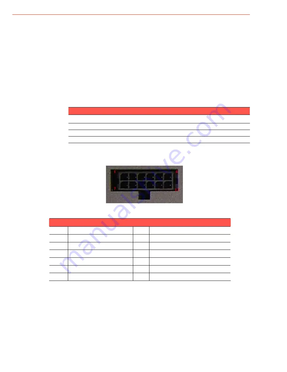
Power
Connector
Figure
2.6.
Power
connector
outlook
Table
2.2.2
Pin
definition
of
Power
Connector
(Molex
Manufacturer
part
no.0430451200)
Pin
Signal
Pin
Signal
1
Chassis
Ground
2
Ground
3
Ground
4
(Reserved)
5
(Reserved)
6
(Reserved)
7
Power
Input
(6~36
VDC)
8
Power
Input
(6~36
VDC)
9
Acc
Ignition
Input
10
Ground
11
(Reserved)
12
Power
button
Input
Connector
:
Molex
430451200
Mating
connector:
Molex
0430251200
Summary of Contents for TREK-510
Page 1: ...TREK 510 User manual 1 User Manual TREK 510 In VehicleComputingBox SmartDisplay User manual...
Page 10: ...TREK 510 User manual 10...
Page 17: ...TREK 510 User manual 14 1 3 Dimensions Figure 1 1 TREK 510 dimensions...
Page 46: ...TREK 510 User manual 46 Figure 6 14 Step 4 Choose setup type Figure 6 15 Figure 6 16...
Page 47: ...TREK 510 User manual 47 Step 5 Tap Install button to install SDK Figure 6 17 Install SDK...
Page 65: ...TREK 510 User manual 65 Appendix B C Windows Embedded CE 5 0 Component List This...
Page 87: ...TREK 510 User manual 87...


