background image

1.2General Specifications 

 
General  

z


Dimensions

(WxHxD): 218x151x74.2 mm (8.58"X5.94"X2.92 ") 

z


Weight

:1.8 kg (6.6 Ibs) 

z


Power supply

: ATX type 

Input Voltage:   12V

 dc

 -24 V

 dc,

 3.5A max. 

Output Voltage:  5V@5A, 12V@1A 

z


Power adaptor AC/DC 

Input Voltage: 100~240V ac 

Output Voltage:[email protected] 

z


Disc Driver housing

: Space for one 2.5”HDD. 

z


Front Panel

: IP65/NEMA compliant. 

Standard PC functions 

z


CPU:

 Onboard VIA Eden™ 400 MHz processor 

z


BIOS

: Award 256 KB Flash BIOS.   

z


System Chipset

: VIA PN 133T Chipset                        

z


Front Side bus

:133 MHz 

z


2nd level cache

: 64 KB on the Eden processor. 

z


System Memory

: One 144-pin SODIMM socket up to 512 

MB SDRAM 

z


Series ports:

 Two serial ports with two-232 ports, one is 

RS232 ports; the other is RS-232/422/485 port. All ports are 
compatible with 16C550UARTs, +5V/+12V power supply 
selectable. 

z


Universal serial bus 

(USB port: Support up to one USB port 

and Intel UHC1v1.1 compatible. 

z


SSD:

 Built in Type 1 Compact Flash socket, supports 

Compact Flash card shared with one IDE channel. 

z


Watchdog timer

: 62-level, internal 1~62 seconds. 

Automatically generates system reset or IRQ11 when the 
system stops due to a program error or EMI. Jumperless 

Summary of Contents for PPC-L60T

Page 1: ...IA Eden Processor based Fanless Panel PC with 6 4 TFT LCD Contents Chapter 1 General information Chapter 2 System Setup Chapter 3 Jumper Setting and Connectors Chapter 4 Hardware Installation and Upgr...

Page 2: ...er friendly as a multi function computer For system integrators this simple complete compact and high integrated multimedia system lets you easily build a panel PC into your application Common industr...

Page 3: ...N 133T Chipset z Front Side bus 133 MHz z 2nd level cache 64 KB on the Eden processor z System Memory One 144 pin SODIMM socket up to 512 MB SDRAM z Series ports Two serial ports with two 232 ports on...

Page 4: ...nuous Light Transmission 80 Controller USB interface Software Driver Support Windows 98 2000 XP Durability 10million Touch in a lifetime Optional modules Memory up to 512 MB SDRAM Standard is built in...

Page 5: ...cd m2 z Temperature 50 C z Backlight Lifetime 20 000hrs Note The color LCD display installed in the Panel PC is high quality and reliable However it may contain a few defective pixls which don t alwa...

Page 6: ...ors and ports which are illustrated in the figures as below When you place the Panel PC upright on the desktop its front panel appears as shown in the Figure 2 1 When you turn the panel PC around and...

Page 7: ...Switch on the power Switch on the power switch on the rear cover 2 3 Running the BIOS setup program Your Panel PC is likely to have been the properly set up and configured by your dealer prior to deli...

Page 8: ...de setup program which automatically load and guide you through hard disk preparation and operating system installation The guidelines below will help you determine the steps necessary to install your...

Page 9: ...The various drivers and utilities in the CD ROM disc have their own test files which help users install drivers and understand their functions These files are a very useful supplement to the informati...

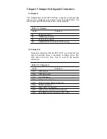
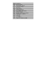
Page 10: ...m reset button JP1 COM2 RS232 422 485 WDT setting 3 2 Connectors On board connectors link the PPC L60T to external devices such as hard disk drives a keyboard or floppy drives The table below lists th...

Page 11: ...onnector CN13 IR connector CN14 Audio connector CN15 Parallel port connector CN16 Power HDD LED connector CN17 Ethernet connector CN18 Keyboard and PS 2 mouse connector CN19 USB channel 1 2 connector...

Page 12: ...3 3 Locating jumpers Figure 3 1 Jumper locations...

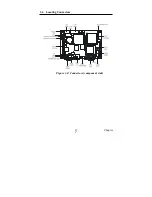
Page 13: ...3 4 Locating Connectors Figure 3 2 Connectors component side 11 Chapter 2...

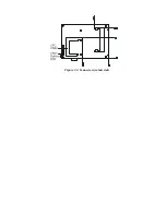
Page 14: ...Figure 3 3 Connectors solder side...

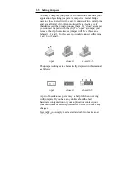
Page 15: ...mper you remove the clip Sometimes a jumper will have three pins labeled 1 2 and 3 In this case you would connect either pins 1 and 2 or 2 and 3 open closed closed 2 3 The jumper settings are schemati...

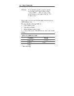
Page 16: ...ck to 3 0 V Battery On This jumper is used to erase CMOS data and reset system BIOS informa tion The procedure for clearing CMOS is 1 Turn off the system 2 Short pin 2 and pin 3 3 Return jumper to pin...

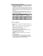
Page 17: ...Open Closed 3 4 Open Closed Open 5 6 Closed Open Open 3 8 hernet configuration The PCM 9373 is equipped with a high performance 32 bit PCI bus Ethernet interface which is fully compliant with IEEE 80...

Page 18: ...setting JP1 as shown below Table 2 6 JP1 Watchdog timer action Pins System reset IRQ11 7 8 closed open 9 10 open closed Default setting 3 10 USB connectors CN19 The PCM 9373 board provides up to four...

Page 19: ...e Panel PC you should be aware of this 4 2 Installing the 2 5 Hard Disk Drive HDD You can attach one enhanced Integrated Device Electronics IDE Hard disk drive to the panel PC S internal controller wh...

Page 20: ...Fig 4 1 Fig 4 2...

Page 21: ...Fig 4 3 Fig 4 4...

Page 22: ...nto a panel Panel Mounting can help system integrators conveniently integrate the Panel PC in their system To construct a suitable panel refer the following cutout dimensions diagram Note The panel th...

Page 23: ...Insert the screws from the front side into the holes and tighten them with the nuts provided See Figure E 2 3 The screw size is M3 L L wall thickness 5 0mm 2 Clamper Mount 1 There are four holes locat...

Page 24: ...Figure 5 2 Panel Mounting...

Page 25: ...Figure 5 3 Panel Mounting 5 1 3 Cut out area Refer to Figure 5 3 below for the locations and dimensions for the cut out area and mounting holes...

Page 26: ...Figure 5 3 Dimension of Panel mounting holes...

Page 27: ......

Reviews: