21
PPC-315W/321W-TGL User Manual
C
ha
pte
r 2
Sy
ste
m
In
sta
lla
tio
n a
nd
S
etu
p
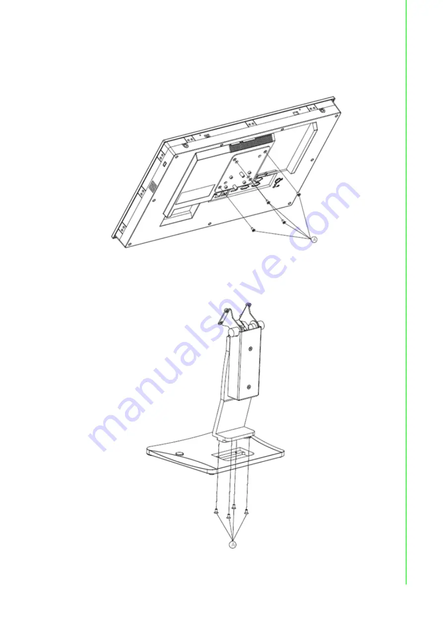
To mount the panel PC onto the stand, follow the steps below:
1.
Use four M4 x 8L screws to affix the VESA bracket to the panel PC. Users can
choose 100 x 100 mm (3.93 x 3.93 in) VESA mount according to their require
-
ments.
Figure 2.27 VESA Mount Screw Holes
2.
Use the four M4 x 8L screws to secure the base plate to the mount stand.
Figure 2.28 Securing the VESA Mount Base
Summary of Contents for PPC-315W TGL
Page 33: ...Chapter 3 3 Jumper Settings Jumpers and Connectors External COM Ports and Pin Definitions ...
Page 37: ...Chapter 4 4 Software Setup Driver Installation BIOS Setup Program ...
Page 42: ...PPC 315W 321W TGL User Manual 34 4 2 4 Security Set Administrator Password ...
Page 45: ...Appendix A A BSMI RoHS ...
Page 47: ...Appendix B B BSMI Series Models ...
Page 49: ...41 PPC 315W 321W TGL User Manual Appendix B BSMI Series Models ...


