20
POC-174 User's Manual
2.2.4 Switching on the power
Switch on the power switch on the rear cover. (See Fig. 2-4.)
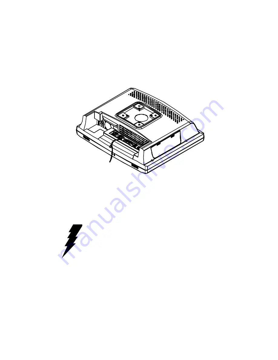
Figure 2-7: Connecting the COM ports (COM 1, 2, 3)
2.2.5 Connecting the COMP ports (COM 1, 2, 3)
Warning!
1. Screw the protective Earth Conductor (Yellow and
green wire) on the nut beside the COM D-Sub
connector. (See Fig 2-7)
2. Connect the COM device to POC-174
Summary of Contents for POC-174
Page 1: ...POC 174 Pentium 4 M processor based panel PC with 17 LCD flat panel display User s Manual...
Page 37: ...24 POC 174 User s Manual...
Page 44: ...Chapter 3 Hardware Installation and Upgrading 31 Figure 3 3 Installing the CPU...
Page 45: ...32 POC 174 User s Manual...
Page 75: ...62 POC 174 User s Manual...
Page 82: ...PCMCIA Introduction Installation of PCMCIA Driver for Windows 95 8 C HAPTER...
Page 85: ...72 POC 173 User s Manual...
Page 90: ...Chapter 9 Touchscreen 77 5 a Touch targets to calibrate the touchscreen controller End...
Page 92: ...Chapter 9 Touchscreen 79 5 a Touch targets to calibrate the touchscreen controller End...
Page 97: ...84 POC 174 User s Manual 9 a Click Finish to complete installation End...
Page 103: ...90 POC 173 User s Manual...
Page 115: ...102 POC 174 User s Manual...
Page 116: ...Mounting Instructions VESA Mounting APPENDIX C...


